This article looks at some basic concepts and misconceptions of AC and DC electrical circuits. There are no formulas involved, just explanations to some commonly asked questions like:
What is AC and DC? What are their differences and what does it matter?
If AC follows a “sine wave” pattern, how do we measure the voltage when it is always moving up and down?
What is “peak power” as apposed to “RMS Power”?
Which way does current flow in a circuit, especially in AC?
What is 3 phase electricity all about?
What does “3 phase, 50Hz, 380 volts” means?
As an introduction to looking at these concepts, mentally picture the following experiments (you can actually do them if you like – they are not difficult).
If you were to measure the voltage from a flashlight battery and plot this voltage every second on a graph, I trust that you would get a result similar to this:
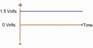 That is, a straight line indicating 1.5 volts continuously (the line would slowly drop slightly from 1.5 volts as the battery went flat).
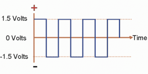
Now if you were to switch the positive lead to the negative end of the battery, and the negative lead to the positive end of the battery, that is, switch it all around, then you should get a result like this:
 This is similar to the first graph, but upside down because it is negative.
Now if you were to quickly switch the leads back and forth, you should end up with something like this:
That is, the voltage is continually going positive, then negative, then positive, and negative again. In other words it is alternating from positive to negative. Hence this alternating nature is commonly called Alternating Current or the shortened form is simply AC. The word current here is used generically, that is although we use “current”, it also relates to the voltage and power.
The converse of Alternating Current, is Direct Current. DC refers to whenever the voltage isn’t alternating between positive and negative, but stays either positive or negative, as shown in the first two graphs. Note that DC can be positive or negative.
AC
Changing a battery around quickly isn’t a very practical way of producing AC. The most common way is by using an alternator (sometimes called a generator, although strictly speaking a generator produces DC, whereas an alternator produces AC).
Other devices that also produce an AC signal are: radio transmitters, inverters and audio amplifiers (e.g. HiFi amplifier).
Let’s consider the voltage produced by an alternator:
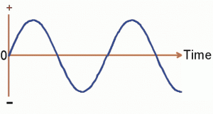 This “sine wave” pattern is the path followed by current, voltage and power in an AC circuit. It doesn’t stay positive or negative for very long, neither does it stay at one particular level. Which begs the question: “How do we measure AC? When we say we have 220 Volts 50 Hz, what does it actually mean?” Let’s look at the 50 Hz part first, as it is the easiest to understand.
Frequency of an AC circuit
The frequency of an AC circuit is simply the number of complete cycles of the wave in one second. This measurement of frequency used to be called “cycles per second” or cps, but these days is called Hertz (Hz) after the German scientist involved in AC circuits.
One Hertz = One Cycle per Second
1,000 Hertz (1kHz) = One thousand cycles per second
1,000,000 Hertz (1MHz) = One million cycles per second
Let’s look at some examples of this:
Example 1: 220 Volts 50 Hz means the voltage goes positive, then negative (one cycle) 50 times a second.
Example 2: 110 Volts 60 Hz means the voltage has 60 full cycles per second.
Example 3: When BBC radio transmits on 15.420 MHz, it means the transmitter is producing complete cycles of AC 15,420,000 times every second.
Example 4: BBC TV satellite broadcasts into Europe use a frequency of 10.995 GHz (Giga Hertz). That is 10,955,000,000 cycles per second!
PRACTICAL POINTS TO CONSIDER
1. In most circumstances it doesn’t hurt to use an appliance on either 50Hz or 60Hz. That is, if a toaster is designed for 110 volts 60Hz, you can use it on 110 volts 50Hz with no apparent difference.
2. AC motors are an exception to the above point. The speed of an AC motor is dependant on the frequency of the supply (an AC motor which has brushes e.g. a portable drill, is not governed by frequency – this class of motor is known as an universal motor, not strictly an AC motor). An AC motor turns faster on 60Hz than on 50Hz. This doesn’t normally worry the motor, but it may affect the performance of the equipment it is connected to. It can also affect the cooling efficiency of the internal fan of the motor.
Example 1: A printing press designed for 60Hz will work fine on a 50Hz supply, but will run 20% slower. Also a supplementary fan may be needed to help cool the motor.
Example 2: A 60Hz photocopier that uses an AC motor to transport the paper through it may not work at all on a 50Hz supply. This is because it transports the paper at a reduced speed, which allows the photocopier to think it has jammed paper, therefore it stops and indicates “paper jammed”. The only remedy is to use it on a 60Hz supply (like a generator).
3. Transformers can be used on either 50Hz or 60Hz without any problem. Often a 220volt/110volt transformer is used to allow a 110 volt 60Hz appliance to be used on a 220 volt 50HZ supply.
Voltage of an AC Circuit
Although here we talk about voltage, the same principles also apply to current and power in an AC circuit.
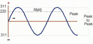
Earlier, we saw that in a DC circuit (a battery) the voltage was a constant 1.5 Volts – pretty simple to measure. However in an AC circuit, the voltage is going from zero volts, reaching a positive peak, falling back to zero, reaching a negative peak and returning to zero again, many times a second. So at what point do we measure it?
If we measured the peak voltage only, then that would be a little misleading, as the voltage is only at this peak level for a fraction of the cycle. Therefore we need to measure it at a point that is sort of average over the whole cycle.
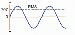 This is basically the effective working voltage, in reality 0.707 of the peak. Officially this is called the RMS of the sine wave. RMS stands for Root Mean Square, which is the mathematicians way of saying 0.707 of the peak, or the effective working voltage
In practice, it is the RMS value that meters are calibrated to read.
Therefore, when you measure 220 Volts on your meter, the peak of the voltage is actually 311 Volts. The peak-to-peak voltage is 622 Volts!
The following chart shows these relationships for common voltages (values rounded off).
| RMS Value | Peak Voltage | Peak-to-Peak Voltage |
|---|---|---|
| 110 | 155 | 311 |
| 120 | 170 | 339 |
| 220 | 311 | 622 |
| 240 | 339 | 679 |
PRACTICAL POINTS TO NOTE
1) A meter reading might deceive you into thinking that a voltage is safe to touch (a very dangerous practice), when in fact it is much higher.
2) A SSB radio transmitter (as used by people to speak long distances) might be rated at 100 Watts PEP. The PEP stands for Peak Envelope Power, which is basically equivalent to Peak-to-Peak. This is the normally accepted method of measuring transmitter power, not RMS. SSB radio transmitters are the only exception, normally all figures should refer to RMS.
3) The power of an audio amplifier should be quoted in watts as “continuous”, “Average” or “RMS”. Beware of advertising which boasts “100 watts peak power!”. Close scrutiny reveals that the RMS value (effective working power) is only 17.5 Watts. Firstly divide the 100 by 2 because it is stereo (100/2 = 50 Watts). Then divide this by two to get peak value from peak-to-peak (50/2 = 25 Watts). Then 0.707 of 25 is 17.5 watts. For more info on Amplifier Power see the article Understanding Amplifier Power.
Calling a 17.5 watt stereo amplifier a 100 watt one, is similar to saying the voltage at the wall outlet isn’t 220 volts, but 1866 volts! That is, the peak to peak voltage times three (for three phases) – slightly absurd.
Changing AC to DC
AC is used in distributing electricity for 2 main reasons:
1) It has less voltage losses than DC, i.e. it is a good way of delivering electricity over long distances through wires because it doesn’t loose as much voltage as DC would.
2) It is easy to change the voltage (using a transformer)
However, apart from motors, heaters and lights, most appliances (especially electronic appliances) use low voltage DC. For example: MP3 players, radios etc work on 3, 5, 6, 9 or 12 Volts.
The best source of pure DC is a battery or a group of batteries (in series) to make up the appropriate voltage. However batteries go flat. That is why most electronic appliances have provision to be run from the AC supply also. It is the job of a power supply to change AC to DC.
Simple power supplies are reasonably cheap. They are often known as “plug-packs”. These are used to power or charge Mobile phones, MP3 players etc. They change AC to DC and often allow different voltages (e.g. 4.5 volts, 6 volts, 9 volts and 12 volts).
Note: Power supplies are designed for certain voltages and certain currents. Be careful not to draw more current than they are designed for.
Current Flow in AC and DC Circuits
Every circuit needs 2 wires: one to carry current into the circuit and one to carry the current out, or to return the current to the source (battery, alternator etc). It is useful to always have the on/off switch in the wire that carries the current to the circuit. Therefore, for this and other reasons, it is good to know which way the current flows in a given circuit.
Unfortunately there is a lot of confusion over which way current flows in a circuit. This confusion has predominantly been raised in technical arguments, most of which have merit. However let us simply use the practical and generally held view that current flows from positive to negative.
In a DC circuit, this is easy to visualise, however what happens in an AC circuit when it is constantly going from positive to negative to positive? An analogy might help: A down hill snow skier is constantly going right – left – right, but still continues in one basic direction. Similarly, even though AC is going positive – negative – positive, basically it is going in one direction. It is easier to use the term “active”, “hot” or “live” for the wire carrying the AC, and the term “neutral” for the return path wire.
Thus we can say in an AC circuit, the current flows from active to neutral.
Three Phase AC
Three phase AC is a very common output from alternators. It is also an engineers delight, when it comes to explaining it. Which is as good a reason as any why we won’t detail it too much. Suffice to say that from the one alternator, 3 separate but related sine waves (phases) are produced (120° out of phase from each other).
It is the relationship between these 3 phases and the neutral that interests us. The basic principle is: Between any 2 phases is one higher voltage, between any phase and the neutral is a lower voltage.
The following table details this relationship for some common voltages.
| Between any phase and neutral | Between any two phases |
|---|---|
| 110 volts | 190 volts |
| 120 volts | 208 volts |
| 220 volts | 380 volts |
| 230 volts | 398 volts |
| 240 volts | 415 volts |
In many countries the supply authority provides 3 phases to each house. When this is done, each phase can be regarded as a separate supply line. That is, the three phases can be regarded as three separate and individual supply lines. Instead of wiring all your house on one single phase. It is often advantageous to spread the load over 2 or 3 three phases.
The advantages of sharing the load over two or three phases are many. The greatest is that you are not dependant on the supply authority to provide good voltage on one phase alone.
PRACTICAL POINTS TO NOTE
1) Three phases and a neutral (4 wires) are often supplied to houses. The two wires for lights and appliances, are connected to any one of the phase wires and the neutral wire, never to 2 phase wires.
2) If the neutral wire is replaced with a phase wire (i.e. accidently swapped), then the voltage is almost doubled. Eg, on a 220 volt system, if the neutral and any of the phase wires are connected in the other’s place (sometimes by the supply authority), then 380 volts will be present instead of 220 volts. This will normally “blow” every light and damage most appliances.
3) Three phase motors require all 3 phases to be connected to them (with or without the neutral – depending on the design of the motor). To change the direction of a 3 phase motor, swap any 2 of the phase wires going into the motor – with the power turned off and the appropriate fuses removed!
SUMMARY
DC is short hand for Direct Current, meaning that the polarity of the voltage remains constant (positive or negative). In a DC circuit, it is generally accepted that current flows from positive to negative. A common source of DC is a battery.
AC is short hand for Alternating Current, meaning the polarity is continually changing from positive to negative. In an AC circuit, it is generally said that current flows from the Active to Neutral. A common source of AC is an alternator, although that may be some distance away (like at the power station), and you receive AC through the wires connected to your house.
The frequency of AC is measured in Hertz, and indicates the number of times per second the voltage goes from positive to negative and back again.
The real working voltage of AC is called the RMS voltage and it is this voltage that meters read when measuring AC voltage.
Most alternators produce 3 active phases, and a neutral. All household appliances and lights should be connected between any one phase and the neutral.

