

This calculator will help you determine the cable losses in distributed speaker systems (also known as 100-volt or 70-volt speaker systems). By inputting the cable size and length, and the number and details of the speakers, it will calculate the loss in SPL(dB), Voltage, and Watts. It even calculates the resultant SPL in dB at the target audience. All you have to do is fill in the white cells in the calculator.
First up, select the units of measure: either “Metres & mm²” or “Feet & AWG”. Most countries use metric, meaning the cable lengths are measured in metres, and the cable size is in mm². USA doesn’t use metric, so select “Feet & AWG” – the cable lengths will be in feet, and an extra box appears to enable you to select the cable thickness in AWG.
Then work your way down the top table:
Total number of speakers connected in the cable run.
Tap settings on speakers: Most speakers for distributed speaker systems have some way of selecting different taps, or power, for the speaker. This is normally expressed in watts.
Speaker sensitivity: this is optional, but is used to calculate the SPL level at the target audience. It is normally found in the specifications of the speakers. For example, a ceiling speaker specs might say “Sensitivity: 90dB (1w/1m)”
Distance from speaker to target audience: This is also optional and is used for calculating the SPL loss in the air from the speaker to the target audience. For a ceiling speaker it might be only 1 metre or so from the ceiling to a person standing. For a speaker outdoors, it might 10 or 20 metres or more.
Total cable length: is the total length of the cable from the amplifier to the last speaker.
Length of feed cable to first speaker should be self-explanatory. It is the cable length from the amplifier to the first speaker. The calculator then assumes the number of speakers are evenly spread over the remaining length of the cable.
Distributed system maximum voltage is about the amplifier. Its output will be rated at 100 volts, or 70 volts, or perhaps 50 or 25 volts.
Cable c.s.a: This is the important figure as all calculations about the resistance of the cable are based on the cross sectional area (c.s.a.) of the cable. This is convenient for metric users as cables are categorised according to their c.s.a. For other users, who are used to sorting their cables according to their AWG number, the calculator inserts the c.s.a for you (based on the AWG # selected).
Once all those inputs are entered, the results are immediately calculated (actually they are calculated after every entry or change). See the remarks below if you need help in interpreting the results. For those who need to know the math behind this calculator, this is explained at the end of this article.
Note: the calculator is best viewed in landscape mode on phones and small screens
| Download Calculator as Excel File |
Prices in US$ |
What the results mean
The results of this distributed speaker system cable loss calculator basically tell you that if you don’t use too many speakers and they are not drawing much power, then you don’t have to worry too much about the cable size. However, if you have long cable runs, many speakers or high power speakers: you may need to reduce the cable length, increase the cable size, reduce the number of speakers and/or reduce the power tap on each of the speakers.
The total load of speakers and cable tells you the total load on the amplifier in ohms. Then the corresponding power from the amplifier is calculated. This figure will be less than the simple calculation of the number of speakers times the power of each speaker. This is because the cable resistance adds to the speaker impedance, which decreases the current from the amplifier, which lowers the total power output of the amplifier. The amplifier needs to cope with this total load. Good practice would dictate that you use an amplifier 20%-25% larger than the total load.
The total cable resistance is for information only.
The maximum current in the feed cable is useful to determine if the cable selected is capable of carrying that current.
The SPL difference between the first and last speaker will help determine if you need to use a larger cable or not. Many systems would cope with a difference of up to 6dB (+/-3dB). Any difference larger than 6dB would become noticeable to many users.
The results for various speakers are then tabulated. Speaker #1 is the first speaker. The results are also shown for the last speaker and the middle speaker. Although the middle speaker number can be changed to see the results of any speaker between the first and last speaker.
The Maximum SPL result is determined by the sensitivity of the speaker, the SPL loss in the air between the speaker and the target audience plus the gain of the speaker over of 1 watt.
Finally, a graph showing the calculated distributed speaker system cable losses is shown.
Assumptions of this Distributed Speaker System Cable Loss Calculator
This calculator makes several assumptions:
- The calculator assumes the resistivity of copper cable is 1.724 x 10⁻⁸ Ωm. This can change slightly between single or stranded cable. Also not all copper cable is pure copper which change the resistivity slightly, as can temperature. Although in practice, these differences will have little effect on the results.
- The calculator assumes the speakers are spread evenly across the cable length (after the feed cable). If the speakers are not evenly spread, there again will be little difference in the results in most cases.
- The calculation for SPL loss in the air between the speaker and the target audience assumes a non-reflective space (like outdoors). For reflective walled spaces the loss could be as much as 6dB less. However the losses will still be relatively the same across the speakers.
- This distributed speaker system cable loss calculator assumes the speakers are all set at the same tapping (watts) and the same size cable is used throughout the cable run. Changes to these assumptions is beyond the scope of this calculator.
Further Information
For further information about distributed speaker systems, also known as 100-volt speaker systems, or 70-volts speaker systems, read the article on Understanding Distributed Speaker Systems
Calculations used in Distributed Speaker System Cable Loss Calculator
You only need to read this if you like to know about the math or you are interested in the principles of the calculations involved. There are a number of steps involved in calculating the cable loss of any circuit.
Calculating the Resistance of the Cable
The first step involves calculating the resistance of each section of cable. The resistance in any cable is determined by the length of the cable, the thickness of the cable and the resistivity of the cable.
The cross sectional area (c.s.a) of the cable is a measurement of how thick the cable is. In the metric system cables are categorized by their c.s.a. For example: 0.75mm2 or 2.5mm2.
The c.s.a. of a non-metric cable is converted from its AWG number (gauge#) to mm2 using the following formula:
c.s.a in mm2 = 0.012668 × 92(36-gauge#)/19.5
Resistivity is the name for the inherent resistance in any material. For copper, resistivity is 1.724 x 10⁻⁸ Ωm. For practical cable loss calculations, simply multiply the resistivity by 10, then divide that by the c.s.a. (in mm2) to get the resistance per thousand meters. For example: let’s say the c.s.a of a copper cable is 2mm2:
1.724 x 10 = 17.24 divided 2 = 8.62 ohms per thousand meters.
If a cable is 100 meters long, then the resistance of the 2mm2 cable would be 8.62 ohms divided by 10 (100 meters is 1/10 of 1000 meters). That is: Resistance of 100 meters of 2mm2 cable is 8.62 divided by 10 = 0.862 ohms
It is important to note that this cable resistance is for a single copper conductor. Speaker cables have two wires, so this resistance needs to be doubled for correct calculations. Once you have the resistance of any length of cable, you can then calculate the losses of that cable.
Calculating Cable Loss
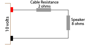
There are two way to calculate the losses of a cable. Both ways require you to know the total resistance of the circuit. Let’s look at a simple equivalent circuit to start with: an amplifier with an output voltage of 10 volts, a speaker with 8 ohms impedance, and a cable with a total resistance of 2 ohms
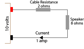
From the above diagram we can see the total load on the amplifier is 10 ohms (8+2). Ohms law allows us to calculate the current through this circuit by dividing the voltage by the resistance. That is, 10 volts divided by 10 ohms results in 1 amp flowing through the circuit.
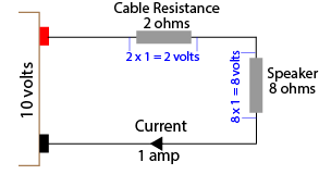
Now that the current is known you can use Ohms law to calculate the voltage loss in the cable and the resultant voltage to the speaker
To do this, simply multiple the current (1 amp) by the resistance. So the cable loss will be 1 x 2 = 2 volts, and the voltage at the speaker will 8 volts. This is the voltage listed in the table as the “Maximum Voltage at Speaker.”
Another way to easily calculate the cable voltage loss and/or speaker voltage is to simply use ratios. The voltage across the speaker can be derived by using the ratio of the speaker impedance to the total circuit resistance. For our example above, the ratio is 8:10, or 4:5 or 4/5 or 0.8 Therefore the voltage across the speaker will be 10 volts x 0.8 which equals 8 volts. This is the method used in the distributed speaker system cable loss calculator. As you can see, either method gets the same result, however the second method doesn’t require the calculation of the current through each circuit.
Calculating Maximum Power at Speaker
The maximum power at each speaker can be easily calculated since the voltage across the speaker and the speaker impedance is now known.
Speaker Power = Voltage squared divided by impedance
Using our simple example, the voltage across the speaker is 8 volts. The impedance is 8 ohms. So the maximum power available at the speaker is 8 times 8 (64) divided by 8 = 8 watts. In the distributed speaker system cable loss calculator this is the figure stated for each speaker for “Maximum power at Speaker”.
Calculating dB Loss
The decibel (dB) loss at a speaker due to cable loss is a calculation of ratios. Either the resistance ratio or the voltage ratio can be used as both ratios are the same.
The formula for calculating decibels may look complicated, but is not too difficult with modern calculators – it just needs the “log” function. Calculators on most smartphones and computers have the log function available although you may need to invoke the scientific calculator option.
Decibel loss at the speaker = 20 times Log(ratio)
Using our simple example, the ratio of the speaker voltage to total voltage (or speaker impedance to total resistance) is 0.8. Using a calculator, log of 0.8 = -0.0969 times 20 = -1.9dB. In the distributed speaker system cable loss calculator this is the figure stated for each speaker for “SPL loss due to cable”. This is the SPL loss from the speaker compared to a circuit with no cable loss.
Calculations for Multiple Speakers
Although the above example is simple, it demonstrates the principles involved in determining the cable loss with one or more speakers. Each additional speaker requires the same calculations as above. There are two main differences. Firstly, the starting voltage for the next speaker will be the calculated voltage from the previous speaker.
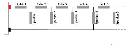
The second difference is how to determine the total resistance for each speaker’s calculation. As can be seen in the above diagram, it is not easy to determine the total resistance. For this reason it is common to determine the total resistance in the circuit based on the total load of the speakers. That is, if there are 20 speakers, each 30 watts, the total load would be 600 watts. Using Ohms law, the total impedance for a 100 volt amplifier can be calculated as 16.67 ohms (voltage squared divided by power).
Alternatively, the impedance of one speaker can be calculated to be 333.33 ohms (again voltage (100 volts) squared divided by the power (30 watts)). The total impedance of 16 x 333.33 ohms speakers in parallel can be calculated as 16.67 ohms.
This figure can be used to calculate the current in the cable to the first speaker, and therefore the voltage loss in the cable and the voltage at the speaker. However the current (and voltage loss) will decrease for each speaker as the number of speakers decreases. So the current in the cable to the 2nd speaker will be determined by the impedance of the remaining 19 speakers in parallel. The 3rd cable’s current will be determined by the impedance of the remaining 18 speakers in parallel. And so on. This is the method used in the first version of the Distributed Speaker System Cable Loss Calculator.
Version 1.2 Changes
The major change in Version 1.2 of the calculator is the inclusion of the cable resistance in determining the total load on the amplifier, and in determining the total resistance for each speaker’s calculations. The first version simply used the calculated load as determined by the speaker impedance (as described above). However as can be seen in the diagram above, if the cable resistance is substantial, it will have some effect on the total resistance and therefore the total load, current and losses.
In version 1.2, the difference in the levels between speakers is normally less than 0.5dB compared to the first version. However the resistance/impedance on the amplifier is increased, therefore the amplifier power and current requirements are slightly decreased. Consequently SPL losses overall are slightly less.