This speaker cable loss calculator simply tells you how much resistance is in your speaker cables and what decibel(dB) and power losses are attributed to your speaker cable. It also calculates the effective damping factor.
This speaker cable loss calculator is designed for low impedance systems – like Hi-Fi, home theatre and other music systems. Low impedance is a term used to refer for systems where the amplifiers are designed for speakers which have a nominal impedance of 2 to 16 ohms. High impedance systems are commonly called 70 volt or 100 volt systems, and are used mostly in commercial installations requiring more than 2 speakers connected to each amplifier. This calculator can be used to calculate speaker cable loss on high impedance systems.
Like all my calculators, simply input the required information in the white cells.
Units of Measure
First up, select the units of measure. Either “Metres & mm²” or “Feet & AWG” can be selected by clicking on the white cell and selecting from the drop down options. Most countries use metric, meaning the cable lengths are measured in metres, and the cable size is in mm². For countries not using metric, select “Feet & AWG” – the cable lengths will be in feet and cable size will be the AWG gauge number.
Cable Length and Size
Then the next two cells to fill in are the cable length and the cable size:
Cable length refers to the length of the cable from the amplifier terminals to the speaker terminals.
Cable size refers to the thickness of the speaker cable. What you enter here depends on the units of measure you chose.
Metres & mm²
Feet & AWG
Enter the Cross Sectional Area (c.s.a.) of the cable in mm² (Eg. 0.75mm² )
Enter the AWG gauge number (Eg. #18 gauge)
Specified Speaker Impedance
Speaker impedance is the impedance stated on the back of the speaker or in the speaker’s manual. It should be specified in ohms (the symbol for ohms is “Ω”). It is normally 4Ω, 6Ω or 8Ω.
Calculated Cable Losses
Once the above values are entered, you can see the calculated results in the box labelled “Calculated Cable Losses”. Here you will see the total resistance of the cable, and the resulting decibel (dB) reduction in power reaching the speaker due to the cable loss.
For many people, that is sufficient information. For example if you just want to know if your cable losses are greater or less than say 0.5dB, then you have that information.
However, if you want to know more about how the cable affects your amplifier and speaker system, then you can add in your amplifier specifications.
Amplifier Specifications
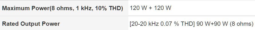
Specified amplifier power should be in the amplifier’s manual or specifications. Keep in mind that some manufacturers only state their absolute maximum power ratings, which are generally not sustainable for longer periods of listening or are come with considerable distortion. I advise you use the most conservative ratings, which should be stated as “Average Continuous Power”, “Continuous Power” or “RMS Power”. A major Hi-Fi manufacturer shows the following in their specifications:
Here they use “Rated Output Power” for their conservative ratings. Notice the THD (Total Harmonic Distortion) is very low (0.07%), unlike their stated maximum power which has 10% THD!
Note that all power output ratings of an amplifier are at a specified impedance. For best results in the calculator, use the stated output power at the impedance closest to your speaker’s impedance. For example, if you have an 8 ohm speaker connected to the amplifier, using the specification above, enter “90” for the stated output power, and “8” for the load impedance.
If the specifications only have a power rating at one stated impedance (Eg: 100 watts @ 4 ohms), use that specified output power and that specified load impedance.
Damping factor should be another listing in the specifications of the amplifier. If it is, and it is something you are concerned about, then also enter the stated amplifier damping factor in the white cell.
If you can’t find the damping factor, or it is of no or little interest to you, then it doesn’t matter.
Calculated Damping Factor & Maximum Power
This box uses a simple diagram to display the maximum power output of the amplifier, the maximum power loss in the cable, and the resulting maximum power reaching the speaker. Note, these values are based on the amplifier running at the specified maximum continuous power.
The calculated damping factor is also displayed in this box.
Note: the calculator is best viewed in landscape mode on phones and small screens
Download Calculator as Excel File
Prices in US$
What do the results mean?
While the results of the above speaker cable loss calculator are theoretically correct, how they are interpreted will depend on which school of thought you subscribe to, how good you think your ears are and how much you care.
Some people suggest the cable losses should be less than 0.3dB. Others say anything less than 0.5dB is not discernible. Others say that if you don’t run the system at maximum power, then simply adjust the amplifier volume control to the level you want and you don’t need to worry about any losses.
Then there is the damping factor to consider (or not). If you’re unaware of damping factor (DF), then there are myriads of articles about it, and just as many suggestions as to what value you should aim for.
Basically, the effective DF indicates the ability of the amplifier to control the speaker’s movement (especially any overshoot). It mainly concerns the low frequencies, and a low DF can result in the some of the low frequencies (like a kick drum) sounding a bit soft or “muddy”.
Some people suggest the effective damping factor should be above 100. Others suggest 50 is good to aim for, and others suggest 10-25 is acceptable. Other people don’t care. It is mostly regarded that the higher the effective DF the better.
The effective DF is mostly determined by the cable resistance and the speaker impedance. An 8 ohm speaker will almost double the effective DF compared to a 4 ohm speaker. Decreasing the cable loss (by using a thicker and/or shorter cable) will increase the effective DF.
Summary
Speaker cable loss is something to be considered, along with many other factors like speaker impedance, sensitivity, power rating and frequency range, amplifier power, and budget.
A thicker speaker cable will decrease the cable loss, increase the damping factor, and increase the cost.
The Audioflow smart speaker switches are a welcome addition to the range of speaker selector switches available to you. Apart from being well made and working well, they also connect to your Wi-Fi and are controllable through your smartphone or Amazon Alexa.
There is a lot to like about these units. They come in three configurations: 2 zone, 3 zone and 4 zone. All three types are the same size and have the same features. As I was supplied with the 4 zone version my comments are about this unit, but the other versions are similar.
Enables connection of 2, 3 or 4 pair of speakers to your Hi-Fi amplifier
Touch buttons to turn each zone on or off
Orange LED above each touch button indicates the state of each zone
Works with amplifiers up to 300 watts @ 8ohms
Uses series/parallel connections for impedance matching
200 Ohm load when no zones are selected
Removable connectors for easier cable connection
Connectors accept cable up to 2.5mm2 or 14AWG
Controllable through smartphone app (iOS and Android)
Controllable through Amazon Alexa
Controllable through external remote switches
Appears to be well made (made in the UK)
Cons
Costs more than a manual selector switch (naturally)
Supplied instructions are basic – need to go to their website for more info
Currently only supports Apple Alexa, not Google Home
Where to Purchase
These units are available through the AudioFlow store at Amazon UK and Amazon USA.
Disclosure: If you purchase these products through the links above I receive a small commission from Amazon which goes towards supporting this website – thanks for you support.
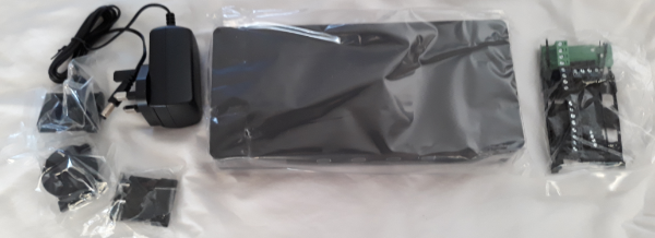
What’s in the box?
The first thing I noticed is what is not in the box. There is no Styrofoam or other packing that needs to be discarded. The main unit is held in place for transport by foldable cardboard tabs. Neither is there any glossy marketing on the box – just a plain brown box.
In the box is the main unit, the power supply and the connections – these are in their own plastic wrapping which does need to be safely discarded.
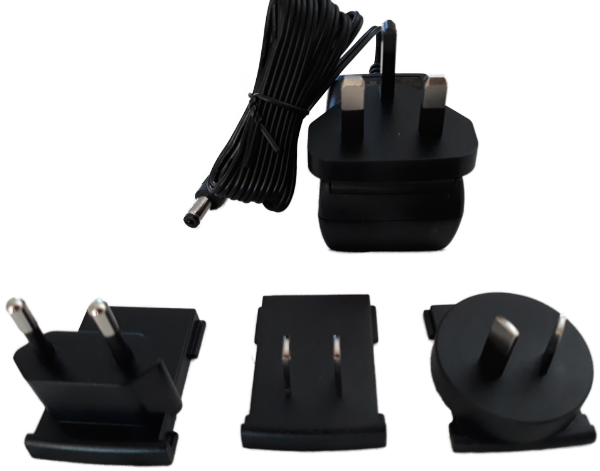
I was pleasantly surprised to see the power supply not only works from 100-240 volts, but also comes with slide on adaptors to fit most power outlets found around the world (USA/EU/AUS). Since these Audioflow smart speaker switches were designed and manufactured in the UK, the UK type plug is fitted to the power supply, but it is simple to change to the type you require. The lead from the power supply is a reasonable length at 1.8 metres, which can be useful in many installs.
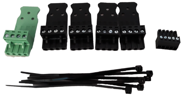
The last plastic bag contains the connectors to attach to your speaker cables. These types of connectors are common on commercial equipment, but not often seen on gear designed for the domestic market. They allow you to screw the cable to the connector without having to be at the rear of the unit (this can be difficult in tight or dark cupboards). The connectors allow up to 2.5mm2 or 14AWG cable to be connected. Once the connection is made, you simply plug the connector into the appropriate socket. They even supply some small cable ties to secure the speaker cable to the connecter as an extra safe guard.
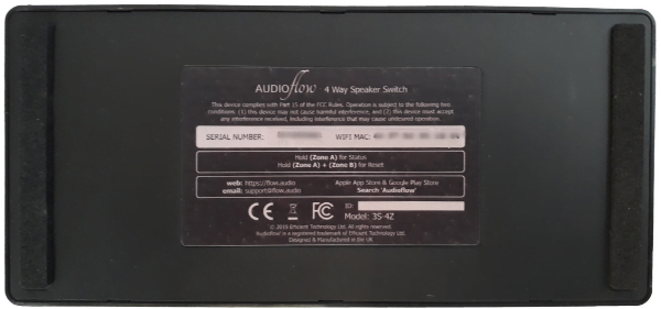
The rear panel has the connection points for the 4 output zones, the amplifier input and the hardwired remote control. The last connection allows physical switches or other control panel/systems to select the output zones.
While the underside of most equipment is boring, there a two things I noted here. Firstly, at either end is a strip of foam padding, which protects this unit from scratching whatever it is sitting on without adding too much to the overall height.
While talking about height, the data sheet says the overall dimensions of these units are 38mm high, 216mm wide and 100mm deep (without connectors). The weight is just 300grams.
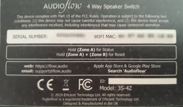
The other thing to note on the underside is the useful information if you lose the instructions.
Here we can see the name of the app to look for on Apple App store or Google Play Store. There is also the simple method to view the status and to reset the unit if required. They even supply an email for you to get extra support if needed.
There is also included an A5 sheet of paper titled “Getting Started“. It points you in the right direction if you know what you’re doing, but there is not much detail. Admittedly, there is not much detail required to connect these units. Further information is available on their website on pages called Using Audioflow in your system and Connecting your Audioflow switch
Turning it on
After making all the speaker connections, it is then a simple matter of connecting the power supply and turning it on. Right out of the box it works like a standard speaker selector switch. Touch the button labelled “Zone B” and the indicator light tells you that Zone B is on. Also the small display tells you Zone B is on and you hear a solid click as the relay turns on Zone B. This is the same for all the zones. Touch a zone button again, and the light and zone turns off (and the display tells you which zone was just turned off).
The zone button switches are not a mechanical switch. They are a touch switch. They don’t need to be heavy duty switches like most other speaker selector switches as they do not need to switch the amplifier power to each speaker. They simply tell the smarts inside that you want to change the state of that zone, and the heavy duty relay inside does the heavy lifting (maximum amplifier power is 300 watts into a total load of 8 ohms).
The display is small, measuring approximately 25mm wide and 15mm high. However it is adequate for what it needs to do. It mostly indicates the last zone that was turned on or off. When you touch a zone button, Eg. “Zone A”, it displays the new state (on or off) of that zone – the display turns off 30 seconds later. After setup with the smartphone app, the display also shows the name of the room for the zone last used:
As well as the small display showing the last action, a small orange LED above each zone button tells you the state of that zone. If you intend to use the touch switches, I suggest you put a label under each button with the name of the zone (eg. Lounge, kitchen).
Of course you probably wouldn’t buy these Audioflow smart speaker switches just to use the touch buttons and small display. Most likely you will use the smartphone app and control it from your phone or through Alexa. I’ll examine the app shortly, but first a word or two about how the smart speaker switch handles speaker impedance – which is a major reason you use a speaker selector switch.
Speaker Impedance
Speaker impedance is a major concern when connecting more than one pair of speakers to your Hi-Fi amplifier. The more speakers you add, the harder your amplifier needs to work to drive those speakers. At a certain point, it will be too hard for the amplifier and it will either shut down, blow a fuse or something worse.
Suffice it to say your amplifier is designed to drive a certain load, measured in impedance. If your total speaker impedance is below what the amplifier is designed for, then you are asking for trouble. Most Hi-Fi amplifiers are designed for load impedance of 4-16 ohms. Some amplifiers like 6-16 ohms or 8-16 ohms.
If your one pair of speakers are say 8 ohms, then there is no problem for the amplifier. However, if you connect 4 sets of 8 ohm speakers, then the total load impedance is 2 ohms – way too low for most Hi-Fi amplifiers. If you want to know learn more about calculating impedance of multiple speakers see my Calculator for Speakers in Parallel.
To overcome these impedance issues with multiple speakers, most speaker selector switches have some method of impedance protection. The Audioflow smart speaker switches use a method called series-parallel. That is, it switches the speakers in a combination of series and/or parallel depending on how many speakers are connected and switched on. The advantage of this method is if you have any one zone selected, then the speakers in that zone are effectively connected directly to the amplifier.
For other combinations of zones, the connections will depend on which model of smart switch you use:
Audioflow 3S-2Z 2 zone smart switch simply connects both zones in series.
Audioflow 3S-4Z 4 zone smart switch connects zones A and B in series, and zones C and D in series, and then connects both sets of series connections in parallel.
Audioflow 3S-3Z 3 zone smart switch connects zone B and C in series, in parallel with zone A.
The above might sound complicated, but it works well. As a simple example, let’s say you have the Audioflow 3S-2Z 2 zone smart switch and two sets of speakers with each speaker being 8 ohms. If you turn on Zone A or Zone B, the speakers in each zone are connected directly to the amplifier, so the total impedance is 8 ohms. Now if you turn on both zones, the speakers will be connected in series, so the total load impedance will be 16 ohms.
The calculations for the 3 zone and 4 zone units get a little more complex. However you can use my Speaker Selector Simulator for series-parallel types to see the result of various combinations of speakers and switching. If there is enough interest, I can create a version of this calculator specific to each Audioflow Smart Speaker Switch.
The units also have a 200 ohm resistor to act as a load when no speakers are selected. This is useful for amplifiers which are not designed for “no load” applications – like valve (or tube) amplifiers.
The “Smart” Part
The smart part of the Audioflow smart speaker switch is the ability to control the switching on your smartphone or through Alexa. First up, you need to download and install the app on your smartphone.
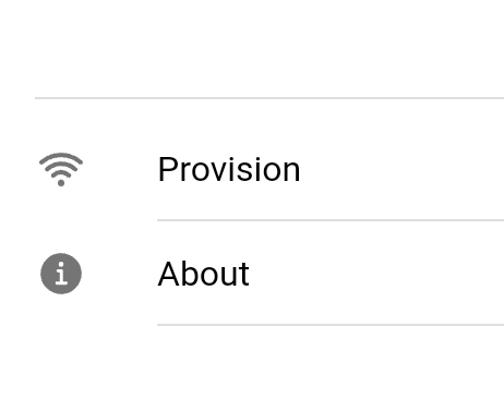
I found the App seemed to be waiting for a connection on the first run of it. Indeed this was the case. I needed to click on the menu bar on the top left of the screen and then select the “provision” option. To my mind “provision” is not the most obvious term, I would have thought “connect device” or something similar would be more obvious. However, once you know “provision” means connect, it is fairly easy going to follow the on screen instructions to connect with the unit and then connect it to your Wi-Fi. I later found instructions called Connect to your Wi-Fi Network are on their website.
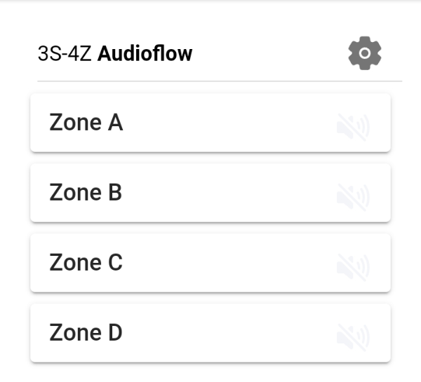
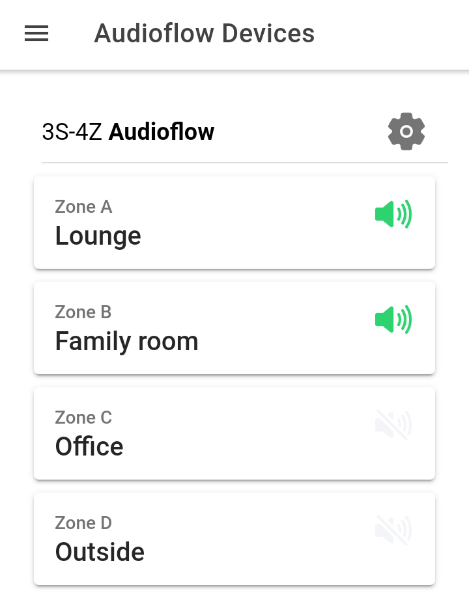
Once connected, the app works well, immediately displaying the connected smart speaker switch with buttons for each zone. Tapping a button turns that zone on/off. However it is best to then tap the setup cog icon in the top right of the screen to go to the setup page.
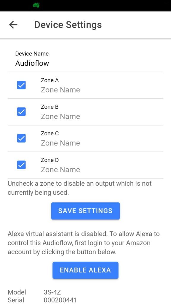
The setup page is quite straight forward. Here you can name each zone like Lounge, Kitchen, Outside etc. These names then appear on the app for each zone and on the small display on the unit itself.
If you are not using all the zones available on your unit, it is wise to de-select the zone(s) you are not using. This inhibits the smart switch from trying to connect that zone in series. This is a convenient feature which is not available on other series-parallel type of switchers.
Further information on using the app and the setup page are available on their webpage, called Using the Audioflow App.
From this setup page you can also enable your Alexa device if you have one. I use Google Home rather than Alexa so I couldn’t try this feature. The instructions on the webpage seem easy enough to follow to set up Alexa. The manufacturer informs me that the Google Home “update” should happen sometime in 2022.
Once setup is complete (and you tap the save button) the app works well with the switcher.
Any changes you make on the app are instantly actioned on the unit. A little green speaker icon appears on the button for each zone which is on. At the same time the little orange LED on the unit comes on above each zone switch and the little display tells you your last action.
If I were to be picky, I would tell you that if you make a change on the unit, the changes are not registered on the app. So it is possible to turn a zone on/off on the unit, but the display on the app will not be updated. If you exit the app and restart it, the app starts with the correct state for each zone. However, I don’t see this as a major issue. I suggest most users will buy these units to use them almost exclusively with the app or by voice commands, and the unit itself will be hidden in a cupboard and not touched. I suspect it is designed this way so the app isn’t constantly polling the unit for its status – which means the app is not using a great deal of your phone’s resources.
On the Inside
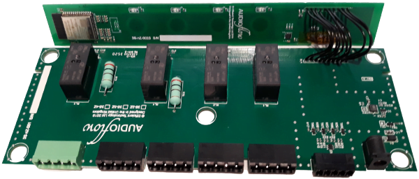
The main board mostly holds the connectors and relays. It has tracks on both sides of the board. The main signal path tracks look solid and are all covered to reduce corrosion. The main board also has the power supply and remote switches control circuitry. All components apart from the connectors, relays and no-load resistors are surface mount devices. The relays are rated at 8 Amps, which means they are well able to switch the maximum rating of the units (300 watts @ 8 ohms).
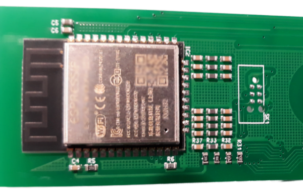
The control board has the touch switches, LEDs, display and “smarts”. The smarts are incorporated in a microprocessor which has built-in Wi-Fi. The antenna for the Wi-Fi can be seen in the little black section adjacent to the processor.
Overall, it appears well made. I could not see any obvious short-cuts in the production methods.
The same boards are used for all three models, with only the number of buttons, relays and connectors needing to be changed.
Summary
Overall these units are a great addition to the range of speaker selector switches on the market. They are well designed and appear well made. I believe they fill a niche which has been vacant for too long. Their flexibility of operation is obviously their strong point, being able to be operated manually, by remote switches, through smartphones and/or through Alexa.
The price is more than a manually operated switch, but given their high amplifier power rating, operating options and impedance matching, they seem a reasonable price. Hey, I just paid $200 to have Wi-Fi capability on my Air Conditioner so I can control it on my smartphone and Google Home, so the asking price for these units seems cheap, comparatively.
Disclosure
I have no relationship or affiliation what-so-ever with the designer or manufacturer of these products, apart from some emails asking me if I would be interested in reviewing their products. The Audioflow S3-4Z model was supplied to me free of charge by them.
I will receive a small commission from Amazon if you buy any of these units through the links supplied above. Apart from that, I have not received, nor will I seek, any payment for this review. I have endeavoured to critique this unit in an unbiased way (although I do like it) with a view to helping the reader decide if it is useful or not for their situation.
This calculator for speakers in series/parallel is a combination of my popular Speakers in Parallel Calculator and my recent Speakers in Series Calculator. It allows you to try various combinations of your speakers in series and parallel to see what the total impedance will be and what effect such a configuration will have on your amplifier.
In fact this could be your on-stop calculator for speaker impedance as it allows you to calculate:
up to 4 speakers in series, or
up to 4 speakers in parallel, or
up to 4 speakers in series in parallel with up to 3 others strings of series speakers.
Not that I normally recommend or condone connecting 16 speakers together this way. But for those readers who like to play around with various scenarios, this calculator will be useful. If nothing else, it will help you realise the problems with connecting so many speakers in series/parallel.
The normal use of connecting speakers in series/parallel is to allow, say, four speakers to be directly connected to a Hi-Fi amplifier without causing overload issues due to impedance. Remember, the total load impedance should be above the designed impedance for your amp. That is, if your amp is specified as 80 watts @ 6 ohms, the total load impedance should be 6 ohms or above.
Impedance Calculator for Speakers in Series/Parallel
Simply type the impedance of each speaker into the white boxes (or use the drop-down values). Use N/A for unused speakers in this calculator. The total impedance of each string will be calculated as will the total load impedance of your configuration. Tip: if only using two strings of speakers in series, ignore the top two strings and only use the bottom two strings.
Also calculated for each speaker is its percentage share of the amplifier’s output power. This is useful as power sharing is a consideration when using speakers with different impedance.
The difference in level between the highest and lowest power through the speakers is also calculated. This is shown in watts and in decibels (dB). This shows the power level difference when using speakers with different impedance.
Amplifier Power Calculator
The bottom section of the calculator helps in matching the speaker combination with your amplifier. This is not necessary if you only want to know the total impedance and/or the power ratios.
However, if you are connecting these speakers to your Hi-Fi amplifier, it may be helpful to input the amplifier power and the associated speaker impedance. In the specifications for your amplifier, it should say something like :
Amplifier power: 80 watts continuous average power @ 6 ohms (2 channels driven, THD 0.08%, 20Hz-20kHz)
This tells you the maximum continuous power the amplifier will deliver into a 6 ohm load is 80 watts. In the calculator below, for this example, you type in 80 for the power and 6 for the impedance. Be aware, some specifications state RMS power rather than continuous power. These are effectively the same.
The calculator will display the effective power of the amplifier for the calculated total impedance of the speakers. Also displayed (under each speaker’s power %) is the actual maximum power the amplifier will supply each connected speaker. A comment on the suitability of the calculated total impedance for your amplifier is also provided.
Note: the calculator is best viewed in landscape mode on phones and small screens
Note: the calculated output power for the amplifier is based on a theoretical “ideal” amplifier. In practise, your amplifier may produce slightly more or less power.
The calculator below is useful in determining the total impedance of speakers in series. It also calculates how the power is shared between the speakers.
Simple Impedance Calculation for Speakers in Series
Do you need a calculator to determine the total load impedance of speakers in series? Probably not. The calculation to determine the total impedance of speakers in series is easy. Simply add the impedance of each speaker to get the total impedance.
Example 1: An 8 ohm speaker in series with a 4 ohm speaker = 12 ohms.
Example 2: Four 4 ohms speakers in series = 16 ohms.
So if calculating the impedance of speakers in series is so simple, why do we need a calculator? My point exactly. I’ve always thought there is no need for such a calculator. After all, most people can add 4+8 and get 12 as the answer. However I’ve had some requests for such a calculator. Hopefully the power sharing calculations are the driving force for these requests and not the total impedance calculation.
Impedance Calculator
Below is my calculator for 2, 3 or 4 speakers wired in series. Although I’m not sure why you would want to connect 4 speakers in series, but if you do, this calculator will help.
Simply type the impedance of each speaker into the white boxes (or use the drop-down values). Use N/A for unused speakers in this calculator. The total impedance will be calculated for the entered speakers.
Also calculated for each speaker is its percentage share of the amplifier’s output power. This is useful as power sharing is a consideration when using speakers with different impedance.
“Power Differential” is the final calculation of the top section. This calculates in dB (decibels) the power level difference between the highest and lowest power as it is shared across the speakers. This shows the power level difference when using speakers with different impedance.
Amplifier Power Calculator
The bottom section of the calculator helps in matching the speaker combination with your amplifier. This is not necessary if you only want to know the total impedance and/or the power ratios.
However if you are connecting these speakers to your amplifier, it may be helpful to input the amplifier power and the associated speaker impedance. In the specifications for your amplifier, it should say something like :
Amplifier power: 80 watts continuous average power @ 6 ohms (2 channels driven, THD 0.08%, 20Hz-20kHz)
This tells you the maximum continuous power the amplifier will deliver into a 6 ohm load is 80 watts. In the calculator below, for this example, you type in 80 for the power and 6 for the impedance. Be aware, some specifications state RMS power rather than continuous power. These are effectively the same.
The calculator will display the effective power of the amplifier for the calculated total impedance of the series speakers. Also displayed (under each speaker’s power %) is the actual maximum power the amplifier will supply each connected speaker. A comment on the suitability of the calculated total impedance for your amplifier is also provided.
Note: the calculator is best viewed in landscape mode on phones and small screens
Note: the calculated output power for the amplifier is based on a theoretical “ideal” amplifier. In practise, your amplifier may produce slightly more power.
This calculator for amplifier power, voltage and current has little significance but is rather interesting.
In the specifications for an amplifier, it might say something like this:
This is telling you the RMS power (or more correctly, the continuous power) with a 8 ohm load and a different continuous power with a 4 ohm load. But what is the peak power? What is the output RMS voltage and peak-peak voltage? What current is the amplifier delivering through the speakers?
This calculator displays the continuous power, peak power, RMS voltage and peak to peak (p-p) voltage. It displays these results in numbers and graphically. It also calculates the RMS current and peak current.
Simply type in the RMS or Continuous power as stated in the specs, and then enter the test load used (eg. 4 ohms or 8 ohms)
Note: the calculator is best viewed in landscape mode on phones and small screens
So what can you do with the results of this calculator? Absolutely nothing!
It is for information only. It is for those of you who like to understand and/or visualize what the specs mean and what your amplifier is doing.
These calculations are for a setup similar to how manufacturers test the power capabilities of their amplifiers. They normally drive the amplifier with a sine wave into a test load (normally 4 ohms or 8 ohms) which is not normally a speaker, but rather a constant value non-inductive resistor.
Amplifier power is probably the most misunderstood and abused parameter of amplifiers and speakers. Yet, it is often the first (and possibly only) parameter people look at when buying an amplifier or speakers.
Marketing managers add to the confusion by using terms like RMS power, continuous average power, music power, peak power, dynamic power, maximum power etc.
Understanding amplifier power will help in understanding the terms often used (and abused) to describe amplifier power. This article will explain what amplifier power is, and what is it is not. Further articles will explain how amplifier manufacturers measure power, what speaker power is and how to match your amplifiers and speakers. Before all that we need to understand amplifier power.
Amplifier Power is Calculated, not Measured
A Voltmeter measures voltage in volts. An Ammeter measures current in amps (amperes). An Ohmmeter measures resistance in ohms. Any two of these measurements will allow calculation of amplifier power (in watts). Unfortunately this means using some math and some formulas. I’ll try to keep it simple and only use one formula. If you like formulas and want to understand how power, voltage, current and resistance inter-relate, you can read my articles on Electrical Power and Ohms law. Otherwise, accept the following formula:
Power = Voltage squared divided by Resistance.
Let’s use this formula with a simple example. Let’s say you have an amplifier connected to a 5 ohm load (I’ve used 5 ohms to keep the calculations simple – normally it would be 4 ohms or 8 ohms for a speaker). With a constant sine wave input, you measure 10 volts AC on the speaker output of the amplifier. Since you know the resistance (5 ohms) and the voltage (10 volts), you can calculate the power:
Power = (10 times 10) divided by 5 = 100/5 = 20 watts.
Simple eh?
Understanding AC Measurements
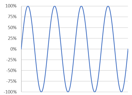
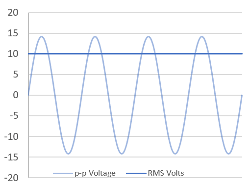
Well that was a simple example. In reality it is not that simple for a number of reasons. The major complication is the output is not a constant level because the input is not a constant level. Let’s start with the simple input of a sine wave. The output would also be a sine wave, like this:
As you can see, the input and output is not constant. It is continuously going up and down, positive and negative. This is the case for any AC (Alternating Current) signal. Yet when you measure it with a meter, you get a constant voltage. This is because a meter tells you the RMS voltage.
RMS stands for Root Mean Square (which you can now forget). It is a mathematical term for what is effectively the working voltage. It is a calculation to determine the equivalent heating effect of a DC voltage. No need to get too involved in how RMS is determined, just remember it is the effective working voltage. It is also the voltage that your meter measures. It is 70.7% of the peak voltage.
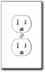
This is the case for all AC measurements. For example, the power outlet in some countries is 120 volts AC – this is the RMS voltage. The sine wave of 120 volts AC goes from +169.5 volts to -169.5 volts or a peak to peak (p-p) voltage of 339 volts. 70.7% of 169.5 volts gives the RMS voltage of 120 volts. In countries using 230 volts, the peak voltage is +/- 325.3 volts.
Measuring Amplifier Voltage and Current
OK, now we know RMS is the effective working voltage (and current) of AC. How does this help us with understanding amplifier power? Glad you asked.
In our simple example above we measured 10 volts RMS at the output of the amp. This means the output actually went from +14.14 volts to -14.14 volts. 70.7% of 14.14 volts is 10 volts.
Calculating Amplifier Power
Now the fun part. We said earlier that power equals voltage squared divided by the resistance. This is true at any point along the sine wave. So if we take the voltage value (shown in blue) and square it (multiple it by itself) and then divide that by the constant resistance (5 ohms), we would get the power output as shown in orange:
A couple if things to note from this graph:
Firstly, AC power does not go positive and negative. It is always positive. Therefore the RMS calculation does not apply.
Secondly, the power is 40 watts peak to peak. However, you can’t say the power of the amplifier is 40 watts because it is only that at the peaks of each sine wave, not at any other time.
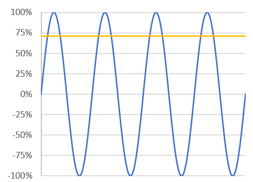
Now let’s look at the RMS values. In our example, we know the RMS voltage is 10 volts. We saw earlier that 10 squared is 100, and 100 divided by 5 gives us a calculated power of 20 watts. Let’s see what happens when we add that to our graph:
Average Continuous Power
That’s right, the effective working power is half the peak power. In fact it is the average of the power sine wave. The average power is the power level the amplifier should be able to produce continuously. Hence it is known as the average continuous power. Specifications should use the average continuous power to state the amplifier power. “Continuous power” is a shortened term of “average continuous power”. Both terms refer to the (average) continuous power, or sustainable power, which an amplifier can produce with the specified load.
In many specifications for amplifier power you will see this referred to as the RMS power. This is not a correct term (because technically there is no such thing). Although the power calculation uses RMS voltage (and/or RMS current if you use other formulas) the result is simply “power”, not RMS power. As shown in the graph above, it is the average continuous power. However, for most amplifier specifications, you can consider RMS power (while an incorrect term) to refer to average continuous power.
Peak Power
Unfortunately marketing people don’t like saying their amplifier has a power of only 20 watts, when they consider they can truthfully say it has a maximum power of 40 watts. Which one would you buy, a 20 watt amplifier or a 40 watt amplifier? When looking at amplifier power, compare apples with apples – always use average continuous power, or the incorrectly termed RMS power (wrong term but correct power value).
However, it is legitimate to say what the amplifier’s peak power is. In the case of our example, it is 40 watts peak. But, peak power should always be accompanied with the phrase “peak power” or something similar. Peak power is often referred to as instantaneous power. Sometimes dynamic power is also used to describe the peak power.
It is important to remember that these descriptions are for the maximum power the amplifier could possibly deliver for a mere fraction of a second. They do not indicate the real long term power the amplifier is capable of producing. It is like saying you can fly a meter in the air because you can jump a meter in the air – for a brief moment. You can’t continually “fly” a meter in the air any more than an amplifier can continually produce its peak power.
PMPO
Peak Music Power Output (PMPO), or Peak Music Power (PMP) is a marketing term that rarely has any resemblance to reality. I prefer to say PMPO stands for Peak Marketing Power Output. It is a term marketers use to make their amps appear as being very powerful. The lower end of the market (like cheaper computer speakers and portable music boxes) tend to use PMPO. If I was to be generous, I would say they arrive at the PMPO value by taking the peak power, multiple it by the number of channels, and then multiple it by some unknown marketing factor between 10 and 1000. For example, the labeling on the box in this picture (brand name removed) claims this unit has a PMPO of 15,000 watts!
Notes about Amplifier Power
Amplifier power is not the only specification you should look at when deciding on a system. It may not even be as critical a factor as you think. For example, the level difference between 60 watts and 80 watts is just over 1dB, which is not very much. To have a 3dB increase in level you need to double the amplifier power. But this doesn’t mean the the volume will be doubled, for that you need to have 10 times the power! For more on this read the article on Double Amplifier Power doesn’t Double the Volume.
If getting the loudest system is your goal, you also need to look at the sensitivity of the speakers. Using a speaker with a sensitivity of 91dB over a speaker with with a sensitivity of 85dB gives a 6dB gain in speaker output for the same signal. This article on Speaker Sensitivity has more details.
Testing amplifier power with a sine wave is a harsh test for an amplifier. It is basically running the amplifier at 100% capacity continuously. A sine wave is not a normal everyday signal. Music and speech have many periods of lower than maximum level, and even pauses. Therefore an amplifier will not be stressed as much in normal use as when it is being stress tested. So some manufactures increase the power rating and use phrases like program power or music power to rate amps. However these ratings are not defined and shouldn’t be used for comparison purposes.
Variables with Amplifier Power
This article has outlined amplifier power, some of the terms used and a basic way of calculating amplifier power. However there are a number of other variables that should be known if you intend to compare amplifiers based on their specified power:
While a simple sine wave is a convenient and relatively easy way to measure and calculate amplifier power, it only measures the power at a single frequency. It should also be capable of this power at other frequencies. Therefore, average continuous power levels should be accompanied by the test frequency or frequency range.
The measured voltage used in the calculation is when the output is at its maximum, with no or little distortion to the signal caused by the amplifier. Some manufacturers measure the amplifier output when running with high distortion, giving an inflated power figure (again this mostly happens on low end products). Therefore, average continuous power levels should be accompanied by the tested signal distortion figures (THD or THD+n expressed as a percentage). This should be 1% or less – the lower the better. Beware of power output figures with 10% THD.
The current, and therefore the power, changes as the load changes. A 4 ohm speaker allows more current than an 8 ohm speaker, so the power produced by the amplifier will change. Therefore, the stated power levels should be at specified test loads.
Ensure the stated amplifier power is with all (or at least 2) channels of the amplifier driven at that power. Some manufactures only give the output power with one amplifier running, which is not a true indication of what the amplifier power supply can deliver when all channels are running.
All this is saying that you need to look closely at the specifications when comparing amplifiers by their power. Ideally, amplifier power should be stated similar to the following:
Amplifier power: 80 watts continuous average power @ 8 ohms (2 channels driven, THD 0.08%, 20Hz-20kHz)
Summary
We have seen through using a simple example that the best value to use for stating and comparing amplifier power is the average continuous power or other synonymous terms. Most terms using “peak” refer to possible power for very short time periods and are commonly used to inflate the real sustainable power levels.
The next article looks at real-world ways of how amplifier power is calculated, including some of the standards amplifier manufactures should adhere to for these tests. This will help in understanding some of the acronyms used like IEC, AES, DIN and FTC.
Before moving on, the following are two more terms that are useful to understand when talking and/or reading about amplifier and speaker power.
Clipping
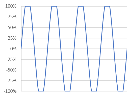
If the input signal is amplified such that the output is larger than the voltage limits of the amplifier, the sine wave will be clipped at the top and the bottom.
This graph shows the sine wave amplified to its maximum level without clipping. This is the level that should be measured for maximum power calculations.
This graph shows the sine wave over-driven by the amplifier such that it is clipping at the top and bottom. This distortion is not just annoying to the ear, it also stresses amplifiers and speakers and should be avoided.
Crest Factor
Crest factor is the ratio of the peak power to the average continuous power, expressed in dB. In our example, the peak power is 40 watts, the average continuous power is 20 watts. This is a ratio of 2:1 or 3dB. An amplifier tested using a simple sine wave (as in our example), will always have a crest factor of 3dB. That is, for a simple sine wave, the peak power is always going to be double the average continuous power.
For live music, with drums and other percussive instruments, the crash/bangs (peaks) could be 10-15 times above the average levels – that is a crest factor of 9-12dB. The table below outlines the relationship between decibels and the peak power to average power ratio.
Crest Factor
Power Ratio
3dB
2:1
6dB
4:1
9dB
8:1
12dB
16:1
15dB
32:1
These figures will be useful as we look at how to match speakers to an amplifier.
This distributed speaker system SPL calculator takes the guess work out of which speaker tap to use. It will tell you the correct power tap for each speaker in your design. The calculator is really useful when balancing levels of different speakers. Or when the speakers are mounted at varying distances from the listener. It also helps in determining the amplifier power needed to deliver the required Sound Pressure Level (SPL) at the target audience.
For those who have played with this calculator previously, a blank version for use is just below. If you want to play with a working example of the calculator to see it in action, click here. If you need help in using the calculator, below is an explanation of all the fields and some user tips.
For further information on distributed speaker systems (often called 100-volt or 70-volt speaker systems) see my article on Understanding Distributed Speaker Systems.
Note: the calculator is best viewed in landscape mode on phones and small screens
Download Calculator as Excel File
Prices in US$
Explanation of Distribution Speaker System SPL Calculator
As with any of my calculators, you just need to fill in the white blank fields. A short explanation of each field follows.
Starting with the table at the top of the calculator:
Select the units of measure, either metres or feet. The selected unit of measure will be used for the distance from the speaker to the target audience.
Enter the required SPL at the target audience. This will depend on the ambient noise level, the purpose of the sound system (background or foreground) and how loud the system needs to be among other factors. As a guide:
65dB – 75dB for quite areas like offices
75dB – 85dB for louder areas like shops
85dB – 95dB for loud places like sporting fields
Select amplifier power output. Most SPL calculators tell you the maximum SPL possible with the amplifier running at full power. This distributed speaker system SPL calculator will do that and more, (or should I say, and less). If required, you can select full power if you want the amp to run at full power with no headroom. Simply select “Full”
You can also calculate the SPL and speaker power taps with the amplifier running at less than full power, which is often the case, and mostly preferable. As the amplifier output power is reduced, the effective power of any connected speaker is similarly reduced, as is the amplifier output voltage. For your information, the following table shows the power and voltage levels along with the effective power rating of a 30 Watt 100 volt speaker for various levels.
Amplifier Power
Amplifier Voltage
Power of 30 watt
100 Volt speaker
Full
100 volts
30 Watts
1/2 power (-3dB)
70.7 volts
15 Watts
1/4 power (-6dB)
50 volts
7.5 Watts
1/16 power (-12dB)
25 volts
1.875 Watts
Low power (1/100, -20dB)
10 volts
0.3 Watts
I suggest you try “1/16 (-12dB)” first. If the speakers can deliver the required SPL at this power setting, then the amp is not going to work hard and you have plenty of room for extra level if required. If this selected level doesn’t deliver sufficient power, try “1/4 (-6dB)”, as this level stills offers headroom.
Select the acoustic space reflectivity/reverberation. This is where any pretense of this calculator being accurate goes out the window. The calculation for SPL loss in the air is based on having no reflections to allow the sound the decay naturally. Specially designed rooms or outdoors are common examples of “dead” acoustic spaces. In such cases, select “Dead”, and no allowance will be made for reflections.
In most rooms there will be some reflections which decrease the natural losses. This calculator allows you to select if the reflectivity or reverberation of the room is judged to be Low, Mid or High.
Low (+2dB) would be for a space with lots of curtains, carpeted floor and soft furnishing. The small reflections within the room wont allow the sound to decay as well as if in the open air. So the air loss might be around 2dB less than in the open air. Or in other words, the sound level at the target audience might be increased by around 2dB.
Mid (+4dB) would be for a space with some reflections which might add around 4dB to the SPL at the target distance.
High (+6dB) would be for a space that is highly reflective with substantial reverb. Large rectangular spaces with wood or concrete floors, and acoustically reflective walls will often increase the SPL to around 6dB at the target audience.
The selection you make here is very subjective, and maybe a guess, but at least you have the ability to allow for the different acoustic spaces. If in doubt, choose “dead” for outside open areas, and “Mid(+4dB)” for indoors.
Calculate Speaker Taps
OK, you have now entered the required SPL, amplifier power setting and selected the acoustic space. Now you can now have fun with different speaker arrangements and calculate the tap setting required.
Start with “Speaker 1” and work down the table for each speaker. The calculator allows up to four speaker types to be calculated.
Speaker Description: This field is optional. It can be used to describe the speaker and anything unique to it. For example, a ceiling speaker might be mounted at a height of 3.2 metres. A while a similar speaker might be mounted on ceiling that is 5.2 metres high. There might also be a box type speaker mounted 5.2 metres high. Entering these descriptions for each speaker install is useful to avoid confusion. If entered, these descriptions are also used in the graph at the bottom of the calculator.
Speaker Sensitivity: This figure is normally found in the specifications for the speakers. For example, a ceiling speaker specs might say “Sensitivity: 90dB (1w/1m)”. For an explanation of speaker sensitivity and how we use it to determine the SPL of a speaker, see my article “Understanding Speaker Sensitivity“
Distance to Target: This is the distance from the speaker to the listener. For ceiling speakers it would be the height of the ceiling minus the sitting or standing height of the listener.
Once these figures are entered, the following are calculated for each speaker:
SPL loss due to Distance: This is the SPL loss through air. This figure is dependent on the distance between the speaker and the listener, and the acoustics of the room/space (that you entered at the top of the calculator).
Required Speaker gain over 1 watt: We hardly need a spreadsheet to calculate this. It is the SPL of the speaker at 1 watt, minus the air losses, compared to the required SPL. In the example calculator below, speaker 3 will produce 84dB with 1 watt going into it, when you measure the SPL 1 metre away. So 84 minus the air loss (8dB) leaves us 76db. This is 6dB below the required 82dB, so the required gain from the speaker is 6dB. This is how much power over 1 watt we need from the amplifier for the speaker output to reach the required SPL.
Speaker power required: This calculation converts the required dB gain over one watt into watts. It also takes onto account any “de-rating” of the speaker power due to it not being driven to full capacity (see table above). This figure is the theoretical value the speaker tap should be set at to attain the required SPL at the target distance.
However, most speakers will not have a tap at that precise level. So, on the next line you need to input the value of the closest tap to the theoretical level.
Actual power tap setting: In the example below, the theoretical speaker power required for the ceiling speakers is 1 watt and 4 watts. However let’s say our ceiling speakers have taps at 10, 5, 2.5 and 1.25 watts. For speaker 1, we could use 1.25 watts instead of the theoretical 1 watt. For speaker 2 we could use 5 watts, instead of the theoretical 4 watts. Speaker 3, the box speaker might have taps at 30, 15, 7.5 and 3.75 watts. Choosing 15 watts instead of the theoretical value of 16 watts, results is only 0.3dB difference in SPL at the target audience distance.
Calculated SPL at target: is the SPL at the target audience distance with the actual speaker power tap. These results are displayed in the graph at the bottom of the calculator.
Difference to required SPL: is the difference between the calculated SPL for the speaker tap, and the required SPL. This number will be positive if the speaker output is above the required SPL. It will be negative if it is below the required SPL. If the difference is only 1-2 dB, it will be barely noticeable. If the difference is over 6dB, then a different speaker or different tap should be used.
The graph reflects any change to any of the values in the tables. It is interesting to change the amplifier power to “Full”, you will see the SPL level raises, as you would expect. However, the dB difference between any of the speakers to each other is the same.
Once you know what taps you will be using for each speaker type, you can multiply the number of similar speakers by the actual tap value to determine what size amplifier you should use. Keep in mind, that good practice suggests to use an amplifier 20-25% greater than the total load.
This calculator will help you determine the cable losses in distributed speaker systems (also known as 100-volt or 70-volt speaker systems). By inputting the cable size and length, and the number and details of the speakers, it will calculate the loss in SPL(dB), Voltage, and Watts. It even calculates the resultant SPL in dB at the target audience. All you have to do is fill in the white cells in the calculator.
First up, select the units of measure: either “Metres & mm²” or “Feet & AWG”. Most countries use metric, meaning the cable lengths are measured in metres, and the cable size is in mm². USA doesn’t use metric, so select “Feet & AWG” – the cable lengths will be in feet, and an extra box appears to enable you to select the cable thickness in AWG.
Then work your way down the top table:
Total number of speakers connected in the cable run.
Tap settings on speakers: Most speakers for distributed speaker systems have some way of selecting different taps, or power, for the speaker. This is normally expressed in watts.
Speaker sensitivity: this is optional, but is used to calculate the SPL level at the target audience. It is normally found in the specifications of the speakers. For example, a ceiling speaker specs might say “Sensitivity: 90dB (1w/1m)”
Distance from speaker to target audience: This is also optional and is used for calculating the SPL loss in the air from the speaker to the target audience. For a ceiling speaker it might be only 1 metre or so from the ceiling to a person standing. For a speaker outdoors, it might 10 or 20 metres or more.
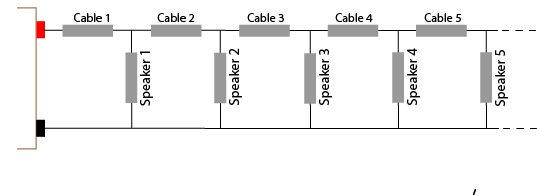
Total cable length: is the total length of the cable from the amplifier to the last speaker.
Length of feed cable to first speaker should be self-explanatory. It is the cable length from the amplifier to the first speaker. The calculator then assumes the number of speakers are evenly spread over the remaining length of the cable.
Distributed system maximum voltage is about the amplifier. Its output will be rated at 100 volts, or 70 volts, or perhaps 50 or 25 volts.
Cable c.s.a: This is the important figure as all calculations about the resistance of the cable are based on the cross sectional area (c.s.a.) of the cable. This is convenient for metric users as cables are categorised according to their c.s.a. For other users, who are used to sorting their cables according to their AWG number, the calculator inserts the c.s.a for you (based on the AWG # selected).
Once all those inputs are entered, the results are immediately calculated (actually they are calculated after every entry or change). See the remarks below if you need help in interpreting the results. For those who need to know the math behind this calculator, this is explained at the end of this article.
Note: the calculator is best viewed in landscape mode on phones and small screens
Download Calculator as Excel File
Prices in US$
What the results mean
The results of this distributed speaker system cable loss calculator basically tell you that if you don’t use too many speakers and they are not drawing much power, then you don’t have to worry too much about the cable size. However, if you have long cable runs, many speakers or high power speakers: you may need to reduce the cable length, increase the cable size, reduce the number of speakers and/or reduce the power tap on each of the speakers.
The total load of speakers and cable tells you the total load on the amplifier in ohms. Then the corresponding power from the amplifier is calculated. This figure will be less than the simple calculation of the number of speakers times the power of each speaker. This is because the cable resistance adds to the speaker impedance, which decreases the current from the amplifier, which lowers the total power output of the amplifier. The amplifier needs to cope with this total load. Good practice would dictate that you use an amplifier 20%-25% larger than the total load.
The total cable resistance is for information only.
The maximum current in the feed cable is useful to determine if the cable selected is capable of carrying that current.
The SPL difference between the first and last speaker will help determine if you need to use a larger cable or not. Many systems would cope with a difference of up to 6dB (+/-3dB). Any difference larger than 6dB would become noticeable to many users.
The results for various speakers are then tabulated. Speaker #1 is the first speaker. The results are also shown for the last speaker and the middle speaker. Although the middle speaker number can be changed to see the results of any speaker between the first and last speaker.
The Maximum SPL result is determined by the sensitivity of the speaker, the SPL loss in the air between the speaker and the target audience plus the gain of the speaker over of 1 watt.
Finally, a graph showing the calculated distributed speaker system cable losses is shown.
Assumptions of this Distributed Speaker System Cable Loss Calculator
This calculator makes several assumptions:
The calculator assumes the resistivity of copper cable is 1.724 x 10⁻⁸ Ωm. This can change slightly between single or stranded cable. Also not all copper cable is pure copper which change the resistivity slightly, as can temperature. Although in practice, these differences will have little effect on the results.
The calculator assumes the speakers are spread evenly across the cable length (after the feed cable). If the speakers are not evenly spread, there again will be little difference in the results in most cases.
The calculation for SPL loss in the air between the speaker and the target audience assumes a non-reflective space (like outdoors). For reflective walled spaces the loss could be as much as 6dB less. However the losses will still be relatively the same across the speakers.
This distributed speaker system cable loss calculator assumes the speakers are all set at the same tapping (watts) and the same size cable is used throughout the cable run. Changes to these assumptions is beyond the scope of this calculator.
Further Information
For further information about distributed speaker systems, also known as 100-volt speaker systems, or 70-volts speaker systems, read the article on Understanding Distributed Speaker Systems
Calculations used in Distributed Speaker System Cable Loss Calculator
You only need to read this if you like to know about the math or you are interested in the principles of the calculations involved. There are a number of steps involved in calculating the cable loss of any circuit.
Calculating the Resistance of the Cable
The first step involves calculating the resistance of each section of cable. The resistance in any cable is determined by the length of the cable, the thickness of the cable and the resistivity of the cable.
The cross sectional area (c.s.a) of the cable is a measurement of how thick the cable is. In the metric system cables are categorized by their c.s.a. For example: 0.75mm2 or 2.5mm2.
The c.s.a. of a non-metric cable is converted from its AWG number (gauge#) to mm2 using the following formula:
c.s.a in mm2 = 0.012668 × 92(36-gauge#)/19.5
Resistivity is the name for the inherent resistance in any material. For copper, resistivity is 1.724 x 10⁻⁸ Ωm. For practical cable loss calculations, simply multiply the resistivity by 10, then divide that by the c.s.a. (in mm2) to get the resistance per thousand meters. For example: let’s say the c.s.a of a copper cable is 2mm2:
1.724 x 10 = 17.24 divided 2 = 8.62 ohms per thousand meters.
If a cable is 100 meters long, then the resistance of the 2mm2 cable would be 8.62 ohms divided by 10 (100 meters is 1/10 of 1000 meters). That is: Resistance of 100 meters of 2mm2 cable is 8.62 divided by 10 = 0.862 ohms
It is important to note that this cable resistance is for a single copper conductor. Speaker cables have two wires, so this resistance needs to be doubled for correct calculations. Once you have the resistance of any length of cable, you can then calculate the losses of that cable.
Calculating Cable Loss
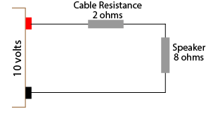
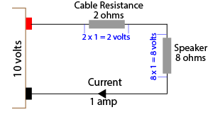
There are two way to calculate the losses of a cable. Both ways require you to know the total resistance of the circuit. Let’s look at a simple equivalent circuit to start with: an amplifier with an output voltage of 10 volts, a speaker with 8 ohms impedance, and a cable with a total resistance of 2 ohms
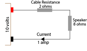
From the above diagram we can see the total load on the amplifier is 10 ohms (8+2). Ohms law allows us to calculate the current through this circuit by dividing the voltage by the resistance. That is, 10 volts divided by 10 ohms results in 1 amp flowing through the circuit.
Now that the current is known you can use Ohms law to calculate the voltage loss in the cable and the resultant voltage to the speaker
To do this, simply multiple the current (1 amp) by the resistance. So the cable loss will be 1 x 2 = 2 volts, and the voltage at the speaker will 8 volts. This is the voltage listed in the table as the “Maximum Voltage at Speaker.”
Another way to easily calculate the cable voltage loss and/or speaker voltage is to simply use ratios. The voltage across the speaker can be derived by using the ratio of the speaker impedance to the total circuit resistance. For our example above, the ratio is 8:10, or 4:5 or 4/5 or 0.8 Therefore the voltage across the speaker will be 10 volts x 0.8 which equals 8 volts. This is the method used in the distributed speaker system cable loss calculator. As you can see, either method gets the same result, however the second method doesn’t require the calculation of the current through each circuit.
Calculating Maximum Power at Speaker
The maximum power at each speaker can be easily calculated since the voltage across the speaker and the speaker impedance is now known.
SpeakerPower = Voltage squared divided by impedance
Using our simple example, the voltage across the speaker is 8 volts. The impedance is 8 ohms. So the maximum power available at the speaker is 8 times 8 (64) divided by 8 = 8 watts. In the distributed speaker system cable loss calculator this is the figure stated for each speaker for “Maximum power at Speaker”.
Calculating dB Loss
The decibel (dB) loss at a speaker due to cable loss is a calculation of ratios. Either the resistance ratio or the voltage ratio can be used as both ratios are the same.
The formula for calculating decibels may look complicated, but is not too difficult with modern calculators – it just needs the “log” function. Calculators on most smartphones and computers have the log function available although you may need to invoke the scientific calculator option.
Decibel loss at the speaker = 20 times Log(ratio)
Using our simple example, the ratio of the speaker voltage to total voltage (or speaker impedance to total resistance) is 0.8. Using a calculator, log of 0.8 = -0.0969 times 20 = -1.9dB. In the distributed speaker system cable loss calculator this is the figure stated for each speaker for “SPL loss due to cable”. This is the SPL loss from the speaker compared to a circuit with no cable loss.
Calculations for Multiple Speakers
Although the above example is simple, it demonstrates the principles involved in determining the cable loss with one or more speakers. Each additional speaker requires the same calculations as above. There are two main differences. Firstly, the starting voltage for the next speaker will be the calculated voltage from the previous speaker.
The second difference is how to determine the total resistance for each speaker’s calculation. As can be seen in the above diagram, it is not easy to determine the total resistance. For this reason it is common to determine the total resistance in the circuit based on the total load of the speakers. That is, if there are 20 speakers, each 30 watts, the total load would be 600 watts. Using Ohms law, the total impedance for a 100 volt amplifier can be calculated as 16.67 ohms (voltage squared divided by power).
Alternatively, the impedance of one speaker can be calculated to be 333.33 ohms (again voltage (100 volts) squared divided by the power (30 watts)). The total impedance of 16 x 333.33 ohms speakers in parallel can be calculated as 16.67 ohms.
This figure can be used to calculate the current in the cable to the first speaker, and therefore the voltage loss in the cable and the voltage at the speaker. However the current (and voltage loss) will decrease for each speaker as the number of speakers decreases. So the current in the cable to the 2nd speaker will be determined by the impedance of the remaining 19 speakers in parallel. The 3rd cable’s current will be determined by the impedance of the remaining 18 speakers in parallel. And so on. This is the method used in the first version of the Distributed Speaker System Cable Loss Calculator.
Version 1.2 Changes
The major change in Version 1.2 of the calculator is the inclusion of the cable resistance in determining the total load on the amplifier, and in determining the total resistance for each speaker’s calculations. The first version simply used the calculated load as determined by the speaker impedance (as described above). However as can be seen in the diagram above, if the cable resistance is substantial, it will have some effect on the total resistance and therefore the total load, current and losses.
In version 1.2, the difference in the levels between speakers is normally less than 0.5dB compared to the first version. However the resistance/impedance on the amplifier is increased, therefore the amplifier power and current requirements are slightly decreased. Consequently SPL losses overall are slightly less.
If you have 2 speakers wired in series, then simply add their individual impedance together. For example: A 4 ohm speaker in series with a 8 ohms speaker: 4 + 8 = 12 ohms.If you have 2 or more speakers in parallel and all the speakers are the same impedance, then divide that impedance by the number of speakers. For example: if you have three 8 ohm speakers, then 8 ÷ 3 = 2.67 ohms.If you have 2 or more speakers in parallel and all the speakers are not the same impedance, then it is easier to use my Speakers in Parallel Calculator.Note: all these calculations are for connecting manufactured speakers (boxes). They are not used when building your own speaker box and connecting multiple speakers in a cabinet using a crossover circuit. A crossover splits the signal into different frequencies for each of the speakers and makes the total impedance calculation complex (as impedance is frequency dependent). That is why speaker designers get the big money, and as installers we benefit from their expertise.
Most Hi-Fi amps require a minimum load impedance of 4 ohms or 6 ohms.
Two 6 ohm speakers in parallel gives a total load impedance of 3 ohms. This is below the minimum of 4 or 6 ohms, therefore it is not advisable to connect two 6 ohm speakers in parallel directly to a Hi-Fi amp.
You can use a 2 zone speaker selector switch which uses a series resistor. This will add a series resistor of 3-5 ohms (depending on the manufacturer.) Therefore the 3 ohms (of the two speakers in parallel) and the series resistor (of the selector switch) will bring the total load impedance above 6 ohms, so all should be good for the amp. However the resistor will reduce the power available to each speaker (by up to 60%). See my speaker selector simulator for more details.
You can also simply connect both speakers in series. This will bring the total load impedance to 12 ohms, which will be fine for the amp as it above its minimum load impedance. However, the maximum power of the amplifier will be slightly reduced. For more practical details see my article on How to connect 2 speakers in series.
For more examples of connecting multiple speakers to a HiFi amp see my article on Understanding Speaker Impedance. The video in this article also describes how the different types of speaker selector switches help with impedance.
Many Hi-Fi stereo amplifiers have connections for Speaker A and Speaker B. These connections are **normally in parallel, so it is the same as connecting two speakers in parallel – but the amp provides switches to turn each set on or off.
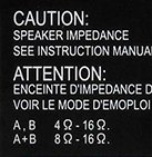
These are designed to allow easy connections of 2 sets of speakers. Normally these amp have a warning notice. This notice is saying that when connecting to either A or B, then the speaker should have an impedance of 4-16 ohms. But when connecting to both A+B, then each individual speaker should be 8-16 ohms.
So if you have 2 sets of your speakers which are 8 ohms or more, then you can safely use these connections. This is because two 8 ohm speakers in parallel gives a total impedance of 4 ohms – the minimum impedance the amp is designed for.
However if your are connecting speakers with an impedance less than 8 ohms, or you have more than 2 sets of speakers, then you should not use these connections as the total impedance will be below the minimum 4 ohms.
For these speakers you could connect them in series to Speaker A only. Or you can use a speaker selector switch connected to Speaker A only.
** Most amplifiers with an A/B switch connect both outputs in parallel, but there are the occasional exception where they connect both outputs in series.
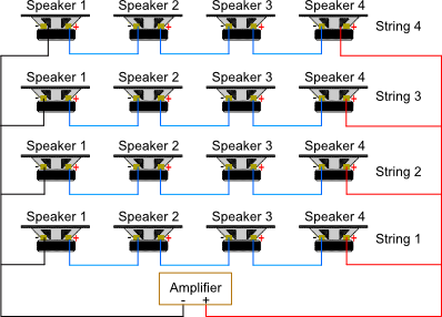
When more one than one speaker is connected to an individual amplifier, they can be wired in series, parallel or (rarely) in series/parallel.
Speakers in Series
Two or more speakers can be wired in series. That is, one wire is used to to go from each speaker to the next. This is not normally used for more than 2 speakers. For a practical discussion on wiring 2 speakers in series, see the article on Connecting 2 speakers to an amplifier.
To calculate the total impedance of speakers in series simply add the impedance of all the speakers together. For example, in the diagram above, if each speaker was 4 ohms, then the total load impedance seen by the amp would be 4 + 4 + 4 + 4 = 16 ohms.
Adding speakers in series is a safe way of adding speakers to an amplifier, but not always practical. The higher total impedance also doesn’t allow the amplifier to produce its maximum power. For more in how impedance changes amplifier power, see the article on How impedance changes amplifier power.
Speakers in Parallel
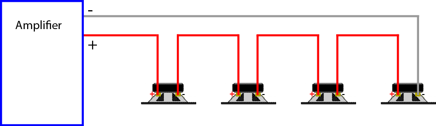
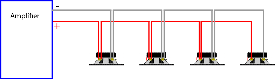
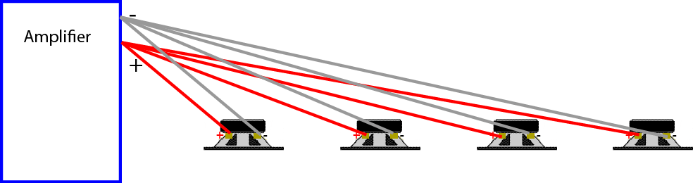
Two or more speakers can be wired in parallel. That is, two wires are used to connected from one speaker to the next.
This is the easiest and most common way of connecting 2 or more speakers. Wiring each speaker back to the amplifier with separate wires is also wiring them in parallel.
Both of the above diagrams show 4 speakers wired in parallel. If you follow each wire with your finger on the lower diagram you will see it is effectively wired the same as the first diagram.
Due to the total impedance, it is rare you can wire more than 2 speakers in parallel.
If each speaker is the same impedance, it is easy to calculate the total load impedance of speakers in parallel. Simply divide the individual speaker impedance by the number of speakers. For example, in the above diagrams, if each speaker is 8 ohms, then the total load impedance would be 8 divided by 4, which equals 2 ohms.
Wiring 2 speakers in parallel is very common in domestic and commercial installs. You just need to ensure the total load impedance of the speakers in parallel is above the minimum impedance required by the amplifier.
If you need to wire more than 2 speakers in a commercial install, there are three alternatives. Firstly you can get commercial amplifiers designed to work with a load impedance as low as 2 ohms. Secondly, you can use multiple amps, That is, one dual channel amp for every pair or for every 2 pairs of speakers. Thirdly, you can use a distributed speaker system.
Impedance is a characteristic of a speaker you need to take note of, especially if connecting more than one speaker to an individual amp. See the article on Understanding Speaker Impedance for details.
The first important point to note is you should not connect a speaker combination with a total impedance lower than the minimum the amp is designed for.
For example, if your amp says the speakers should be 4-16 ohms, then connecting a 4 ohm, or 6 ohm or a 8 ohm speaker is fine. But connecting two 4 ohm speakers in parallel (which results in 2 ohms total load impedance) is too low. To calculate the total impedance of speakers in parallel see the popular Speaker in Parallel Calculator.
If you do connect a total load impedance which is lower than the amp’s minimum, you run the risk of overloading the amp; causing it to turn off, blow a fuse or blow the electronics. You can get away with a lower impedance at low volume levels, but as the amp gets close to its full output, it will get hot and stop working.
The second important point to note is you normally can have a total load impedance above the recommended maximum (Eg above 16 ohms). However the higher the load impedance, the less power the amp will be able to produce. See the article on Speaker Impedance Changes Amplifier Power.
Some amplifiers will detect that the impedance is too high and turn off thinking there is no speaker connected, but most amps will have no problem.
The exception is a tube (valve) amp. Most tube amps require some load and don’t like having no load.
In a perfect world, every cable should be labelled, identifying which speaker they are connected to. However, that is often not the case. Perhaps you are helping a friend, or you have moved into a new house which has speakers in many rooms, or perhaps the kids have pulled the wires out for fun. Whatever the reason, you’ll be pleased to know there is a cheap and easy way to find what speaker each cable is connected to.
You will need two things: someone to help you, and a 1.5 volt battery.
Each cable going to a speaker has 2 wires. Make sure the wires are stripped (that is, the outer plastic is stripped off, allowing around 12mm (1/2″) of bare copper wire to be seen at the ends.
Hold one of the wires (doesn’t matter which one) on the bottom of the battery. With the other wire, tap it on and off the top of the battery (the +ve terminal). The connected speaker will make a scratching noise. Note: the speaker only makes a noise when the wire is tapped on or off the battery. So keep tapping the wire on and off the battery until your assistant finds the speaker which is making the noise.
Once identified, label the speaker cable.
Other Methods
Use an impedance meter: an impedance meter sends a tone (normally 1kHz) down the cable to measure the speaker impedance. Most meters also allow the tone to be held on continuously so you can test and/or identify what speakers are connected. This is a great way as the meter will also tell you the total load impedance.
Connect to amplifier: You can connect the cable under test to an amplifier playing some music at a low volume level. Just be careful not to short the wires when connecting the amplifier. Probably best to turn amp off when making each connection.
You can certainly design your speaker boxes, but I wouldn’t.
I’m an installer, not a speaker designer. I’ve installed many speakers, but I wouldn’t like to try to design them. The internals of a speaker box (cabinet) is complex.
The simple calculation of speakers in parallel is only useful if your don’t use a cross-over circuit (a circuit which splits the signal into different frequencies to best match each speaker in the box).
The complexity of the total impedance of a speaker (box) is not the only issue. Other things I’m aware of (among other issues) that need consideration are:
The internal volume of the cabinet (less the volume of the other speakers) needs to match the characteristics of the biggest speaker
The effect of the air movement caused by one speaker might have on the other speakers
The matching of the crossover circuit to each of the speakers
The phasing of each speaker relative to the other speakers
The overall flatness of the resultant frequency response.
The power handling of each speaker
So, I leave all that to the people who get paid the big bucks to design speakers. We need to simply install and enjoy the product of their effort.
It is not possible to make two 8 ohm speakers into a 8 ohm load.
There are only two ways to connect two speakers together, either in series or parallel.
In parallel, two 8 ohms speakers give a total load impedance of 4 ohms – too low for any amp designed for a minimum load of 8 ohms.
In series, two 8 ohm speakers gives a total load impedance of 16 ohms. This will work with amps designed for a minimum load of 8 ohms. However the amp will not operate at full power. In a domestic install, a simple series/parallel speaker selector switch can be used to do this, as well as enable any one pair of speakers to be connected on their own. However, with a 16 ohm load, the amplifier’s output power will be reduced by 3dB compared to using just one 8 ohm speaker. For more info on this see the article on how Speaker impedance changes amplifier power.
For the best power output, you would be better off to use just one 8 ohm speaker, provided it will cope with the full amplifier power.
So, it comes down to what you are trying to do. If you want maximum power, then use just one speaker. If you want a wider area covered than what one speaker will cover, then use the two speakers in series.
Also if maximum power is not an issue, then you could also use a speaker selector switch with a series resistor. This will add a 3-5 ohm* resistor in series with the speaker. This will allow both speakers to be wired in parallel (4 ohms total load impedance) in series with the resistor (3-5 ohms) to give a total load impedance close to 8 ohms. However the resistor will take close to half the power of the amplifier. This is not normally a problem when using multiple speakers in a house, but not so good in a commercial installation requiring maximum power.
*the value of the resistor depends on the manufacturers design.
To see how much power a speaker selector switch resistor takes, see my simulator here.
If, after reading these FAQs, you still have a question, please ask it in the “comment” box below.
In your question, please include as many details as you can. Include the make and model of the amplifier and speakers as I often try to find the specifications and/or manual for your equipment to better answer your question.
I also ask for your location. This is helpful as some countries have different policies and practices. It also helps me suggest any products and suppliers available to you if you need some extra equipment.
It takes a lot of my spare time answering readers’ questions, so I filter some questions. I may not answer questions, or only give a brief answer if your question is
Already answered in these FAQs
Already answered in my other articles (I expect you to have tried to find a solution yourself)
Off topic.
I trust you can appreciate I only apply these filters to allow me to concentrate on answering those question not already covered.
Speaker sensitivity is a measurement of how well a speaker converts the amplifier power to acoustic energy. In others words, how loud the speaker will be for a given amplifier power.
How Speaker Sensitivity is Measured
Measuring speaker sensitivity is not difficult in concept, but is mainly done by speaker manufacturers and independent consultants.
Basically, the sound output of a speaker is measured with a calibrated sound level meter. To be consistent, speaker sensitivity should be measured 1 meter from the speaker with 1 watt of power coming from the amplifier.
A sound level meter measures Sound Pressure Level (SPL), and is measured in decibels (dB).
Therefore when you look at the specifications for a speaker, you will see something like:
Sensitivity: 87dB (1w/1m)
This means that speaker produces a level of 87dB when driven with 1 watt of power and measured 1 meter in front.
Comparing Speaker Sensitivity
Let’s say you are looking at three different speakers. In the specifications, under speaker sensitivity, for each speaker it states:
Speaker B will be 3dB louder than speaker A. This may not may seem much, but when you realize that 3dB is the same as doubling the amplifier power, it can be significant.
If you want to connect Speaker A and Speaker C to the same amplifier, then Speaker C will be 6dB louder than Speaker A.
When comparing speaker sensitivity figures, keep in mind that different manufactures may arrive at their figures differently. See the section below on “comparing apples with apples” for some of the differences you may come across or need to be aware of.
Sensitivity is just one factor of a speaker, it doesn’t indicate quality or lack of quality. Speaker sensitivity has nothing to do with the sound quality of the speaker, just how loud it will be for a given power input. It is just one issue for consideration when selecting speakers.
How to use speaker sensitivity
Speaker sensitivity can be used to determine how loud your speaker will be in different situations. Alternatively, it can help you determine how powerful an amplifier you will need.
The speaker sensitivity figure tells us how loud the speaker will be with a 1 watt amplifier, and when standing 1 meter away from the speaker. But what happens when you increase the amplifier power, and/or increase the distance? Glad you asked, read on.
What if the power is increased?
As the amplifier power to the speaker is increased above the 1 watt reference, the output of the speaker will increase. Some general rules of thumbs to remember:
Doubling the amplifier power increases the speaker output level by 3dB
Using a 10 watt amplifier increases the speaker output level by 10dB
Using a 100 watt amplifier increases the speaker output level by 20dB
Using a 1000 watt amplifier increases the speaker output level by 30dB
Example 1: A speaker with a rated sensitivity of 87dB (1w/1m) when driven by a 100 watt amplifier (20dB gain over 1 watt) will produce a maximum sound level of 107dB (87+20) when measured 1 meter away.
Example 2: If you stand 1 meter away from a speaker with a rated sensitivity of 87db (1w/1m), then you will hear a level of 87dB if it is driven with 1 watt of power. If you double the amplifier power (to 2 watts) you add 3dB of gain and the speaker will now produce 90dB (87+3). Double the amplifier power again (to 4 watts) and you increase the output by another 3dB to 93dB.
Use this calculator to see how the speaker output changes (when measured 1m away) as amplifier power changes (you can change the sensitivity and amplifier power figures).
What if the distance is increased?
The further you are away from the speaker, the lower the sound level (volume) you will hear from it. You might like to call this “air loss”. That is, this is how much sound level is lost in the air over the distance.
every time you double the distance, you hear a quarter of the sound level
The general rule is every time you double the distance, you hear a quarter of the sound level. Mathematically, the level decreases by 6dB every time you double the distance. If you want to sound technical, this is called the Inverse Square Law.
Example 3: A speaker with a rated sensitivity of 87dB (1w/1m) that is driven by a 100 watt amplifier, will produce a sound level of 107dB (see example 1 above) when measured at 1 meter. Double the distance to 2 meters, and the sound level will drop from 107dB by 6dB to 101dB. Double the distance again to 4 meters will decrease the level by another 6db to 95db.
Use the calculator below to see the level drop for different distances. Note: this rule applies in an ideal acoustic environment (like outdoors with no walls or reflections). Indoors there is often less air loss due to reflections caused by the walls, ceiling and floor.
Increasing power and distance
We have seen that increasing power to a speaker will increase its output level. We have also seen that the further you are away from a speaker, the less you hear.
This handy calculator will show you the level you can expect from your speaker when you know the sensitivity (1/w/1m), the amplifier power, and the distance from the speaker.
Note: The calculation for air loss applies to an ideal acoustic environment (like outdoors with no walls or reflections). Indoors there is often less air loss due to reflections caused by the walls, ceiling and floor. Up to 6dB less air loss could occur indoors (depending on the acoustics).
Beware of the Speaker’s Maximum SPL
When using speaker sensitivity to determine what power amp you should use, be aware of the maximum power your speaker can cope with lest you burn the coil in the speaker. This is normally also stated in the speaker specifications.
Some manufacturers will state the maximum power rating in the specifications. Others will state the maximum SPL of the speaker. In either case, don’t exceed their ratings.
2.83 volts instead of 1 watt
Some specifications don’t use 1 watt at 1 meter to state the speaker sensitivity. Instead they use 2.83 volts at 1 meter.
For an 8 ohm speaker, 1 watt of power from the amplifier is the same as 2.83 volts from the amplifier. As shown in the side box, if an amplifier outputs 2.83 volts into an 8 ohm speaker, then it produces 1 watt of power.
If you like to see a formula:
I understand the measurement standards states the amplifier should be set to output 2.83 volts. Possibly for ease of understanding speaker specifications, this is normally stated as 1w/1m, but is equally correct when stated as 2.83v/1m.
However the same is not true for a 4 ohm speaker. If 2.83 volts from the amplifier drives a 4 ohm speaker, it produces 2 watts of power. So for a 4 ohm speaker, 2.83v/1m equals 2w/1m.
Here’s another formula:
So when reading the speaker sensitivity specification, if you see 2.83 volts as the reference, check the impedance. If the speaker impedance is less than 8 ohms, then it is being driven by more than 1 watt of power.
There are at least two schools of thought on what to do about this discrepancy. One school says this is cheating, as you are driving a 4 ohm speaker with 2 watts, and not 1 watt. Therefore you are already doubling the power (that is, adding 3dB to the speaker’s output). Another school of thought says, hey, that is the inherent sensitivity of the 4 ohm speaker so live with it.
The calculators above are based on 1 watt of input power. So when using 2.83 volts into 4 ohms, you will need to reduce the speaker sensitivity figure by 3dB to obtain the correct result. (Remember doubling the amplifier power (to 2 watts) adds 3dB to the speaker output. So to halve the output (back to 1 watt), you need to subtract 3dB).
Comparing Apples with Apples
We have seen that some manufacturers use 1 watt, others use 2.83 volts as the input level. There are also other differences in how manufacturers measure the sensitivity which are not so obvious, but can make a significant difference.
Some manufacturers measure at just one frequency (probably the most sensitive frequency). Others might measure at several frequencies and then average the results. Others might state each frequency. Pink noise, which is a combination of all frequencies, might be used by other manufactures.
Some testers may measure in line with the most efficient speaker in a cabinet, others might measure at the center axis of the cabinet. Some might do the measurements in a perfect non-reflective environment, others might do in a real world environment. Some might measure further away than 1 meter, and then calculate the 1m figure.
All these differences can subtract from the purpose of having an objective method of comparing speaker sensitivity. These differences are also difficult to ascertain as few manufactures include these details in their specifications.
None the less, using the speaker sensitivity specification should give you a good guide as to how loud a speaker will be at a specified distance and a specified amplifier power input.
Is Speaker Sensitivity and Efficiency the Same?
Speaker sensitively and efficiency are related, but not the same. Although in general discussions among non-technical people the terms are often interchanged – especially by marketing people.
Technically, efficiency is the ratio between amplifier input power and speaker acoustic output power. Efficiency is calculated and stated as a percentage.
The truth of the matter is speakers are not very efficient at converting amplifier power to acoustic power. Speaker efficiency is normally around 0.1% – 2%. This figure is not as useful to us as a speaker sensitivity dB figure which we can easily use in a calculations.
Summary
Speaker sensitivity figures are used to calculate how loud a speaker will be at a given distance and a given amplifier power. It is just one issue for consideration when selecting speakers. It doesn’t indicate sound quality or lack of sound quality.