In an earlier article we looked at the issues involved in connecting multiple speakers to one amplifier. In this article we look at some of the practical ways of wiring four speakers to each amplifier (left and right) . For example, it is normal to have your main HiFi amplifier in the lounge room. It is also common to want to have some speakers in the family room, outside (patio or pool area) and in the workshop or garage.
So let’s look at the various ways of wiring at least 4 pairs of speakers to one HiFi amplifier. If you need to connect just 2 pair of speakers to a HiFi stereo amplifier (that is, 2 speakers to 1 amp), see my article on How to connect 2 speakers to 1 amplifier.

I have had many people over the years tell me it is easy to connect multiple speakers – all you have to do is wire the speakers in series. When I’ve grilled them about how they did that, they say they simply wired them as a “daisy chain”, one after the other. When questioned further, I find they have actually wired them in parallel, and have wondered why the amplifier doesn’t like it.
In the following diagrams I will only show the wiring for one side of a stereo amplifier, let’s say the left side of the stereo. In reality this wiring needs to be duplicated for the right side speakers too.
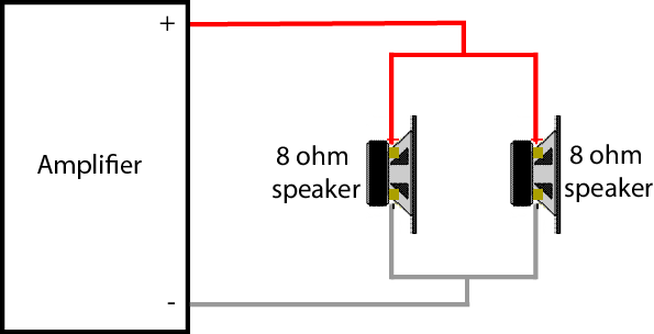
Four speakers wired in parallel
This diagram shows how to wire four speakers in parallel.
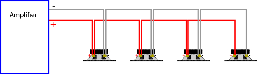
Some people call this “daisy chain” as it connects one speaker after another, but it is really wiring them in parallel.
It is the same as wiring each speaker directly from the amplifier, like this:
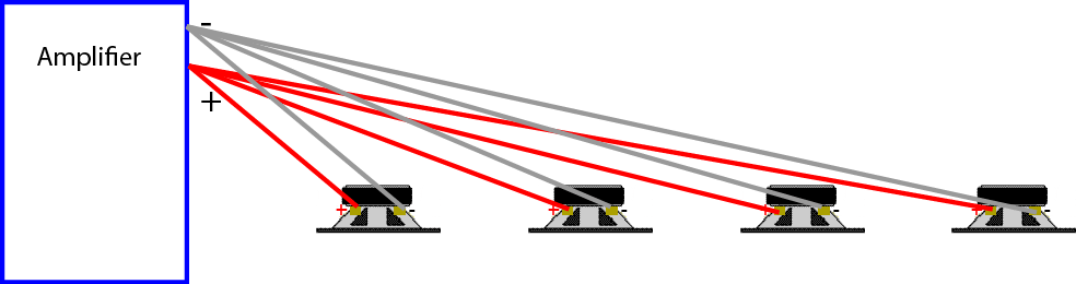
Wiring speakers in parallel is not a good way of connecting three, four or more HiFi speakers as it puts too much load on the amplifier (as explained in earlier article)
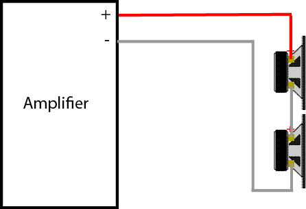
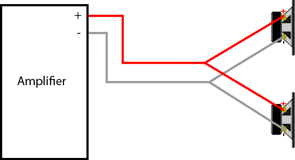
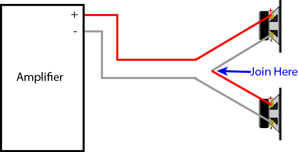
Four speakers wired in series
This diagram shows how to wire four speakers in series.
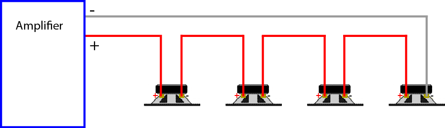
Again this is not a recommended way of wiring four speakers (although it will work), nor is it very practical. Apart from the hassle of having to wire from one speaker to the next, if one wire is disconnected, then all speakers will stop working. Also each speaker affects the total load seen by the amplifier which will only allow it to work up to one eighth of its potential. This is closer to a daisy chain as each speaker and corresponding single wire forms part of a daisy chain loop.
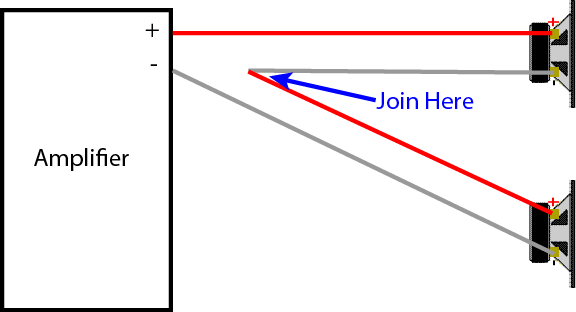
Four speakers wired in Series-Parallel
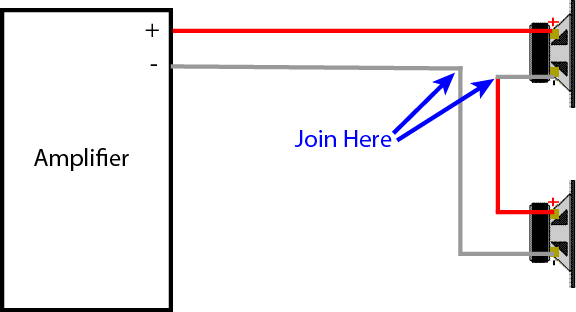
This diagram shows how to wire four speakers in series-parallel.
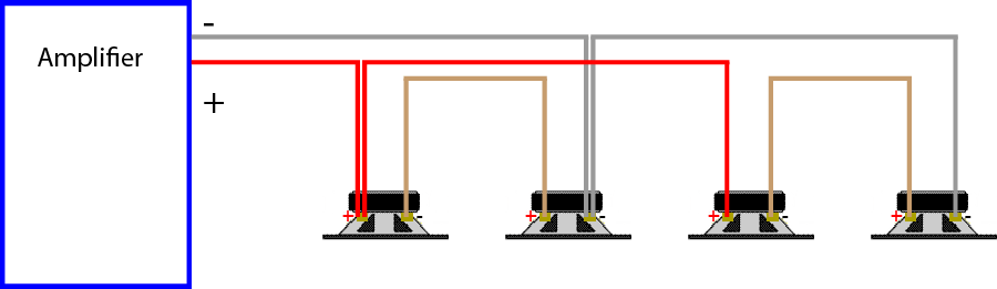
This is a safe way of wiring four speakers (without a switch box or separate volume controls). It is a combination of series and parallel. Providing all the speakers are 8 ohms, this will work as the total impedance is also 8 ohms,
While this will technically work, it is often not practical as you need lots of wires interconnecting all the speakers and there is no control over any one speaker – they all are controlled by the amplifier volume control at the same time. This is not good if you only want music in one area of the house, and not everywhere at the same time – apparently neighbours don’t always like listening to the same music as you (through the outside speakers).
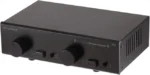
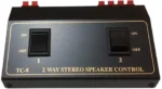
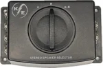
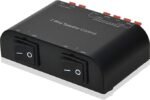
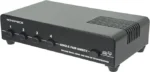
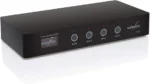
Speaker Selector Switch
The easiest and a safe way to connect 4 pairs of HiFi speakers is to use a 4 zone speaker selector switch.
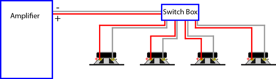
This is relatively simple to wire, just run a wire from the central location (lounge room) to each speaker. The box should also look after any impedance matching to prevent amplifier overload. Although the volume will be similar in all areas, at least it is possible to turn off the speakers in the areas you don’t want sound. It is normal to locate the selector switch adjacent to the amplifier. Remember to connect the lounge room speakers to one switch so they can be turned off when you only want music outside.
Please note, speaker selector switches are designed for multi-room installs in a home. They are generally suited for low power (under 100 watts) amplifiers. They should be not be considered in a commercial install or for use with high output power amplifiers.
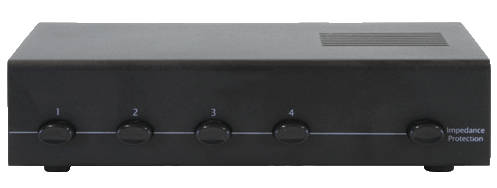
Speaker selector switches can use various techniques to allow multiple speakers to be connected to the one amplifier, namely:
- a series resistor (around 2½ – 5 ohms) to restrict the minimum impedance of the speakers circuit to this value. This simple series resistor if often marketed as “manual impedance protection”. They are normally good for lower powered speakers, and the resistor can get hot at high volume levels. If this switch is not selected, you have no protection when running all the speakers together.
- combining the different speakers in series and/or parallel to keep the overall impedance above 4 ohms. This is similar to the series-parallel wiring above, but it all happens in the box for you.
- matching impedance transformers – this is the best, but it is also the most expensive.
All these methods allow multiple speakers, but at a lower volume than using just one speaker. This is logical as the signal is being shared by more than just the one speaker. To see how the power is distributed by the different types of speaker selector switches, see my Speaker Selector Switch Simulator.
If you are interested in using a speaker selector switch, check out my summary article on speaker selector switches – it discusses the features and uses in more detail, and summarises all the units bought from Amazon through this web site. You can also download the user’s manual for most models – before you buy it.
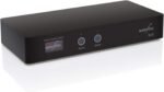
There are also available speaker selector switches which can be controlled through your smartphone or Alexa. Geoff has written a review of the Audioflow series of switches which you can read here.
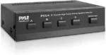
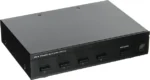
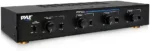
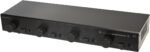
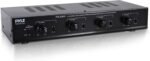
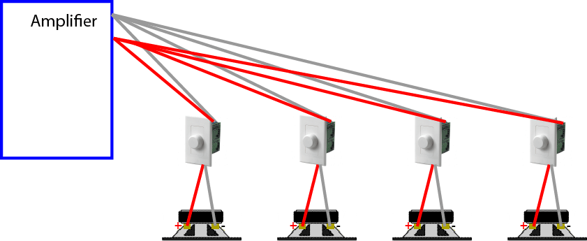
Speaker Selector with Volume Controls
A more practical (and a little bit more expensive) way it to substitute the selector switch with a unit that also has volume controls. This allows the volume in each zone (area with a pair of speakers) to be controlled at the central location.
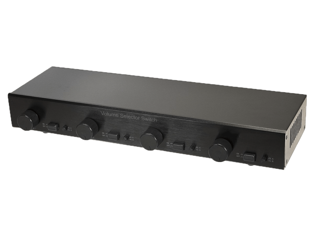
Some volume control units also have impedance matching. This means they have a switch (normally on the back panel – but sometimes inside) which allows you to tell it you are connecting 2, 4 or 8 pairs of speakers to the one amplifier. Once this switch is set, you don’t need to worry about overloading the amplifier. Some units don’t have a switch but are set for four speakers. Impedance matching works by appearing to the amplifier as just one speaker, while it evenly splits the signal to all four speakers – in reality, each speaker only gets 1/4 of the sound that comes from the amplifier (assuming you selected x4 on the switch).
Other volume control units (read cheaper) don’t have impedance matching. These units rely on you probably not needing to run all four sets of speakers flat out at the same time. While this is not as safety assured as using impedance matching, it may suit some installations. If you only want low level music in the workshop and family room, then this will be fine. If you are having a party and want loud music outside, just make sure the workshop and lounge room are turned down – this reduces the total load and this effectively means only one or two pairs of speakers are connected to the amplifier.
Remember to allow a volume control for the lounge room speakers so they can be controlled also.
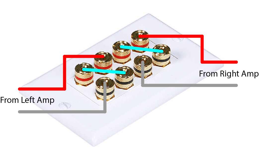
In-Wall Volume Controls
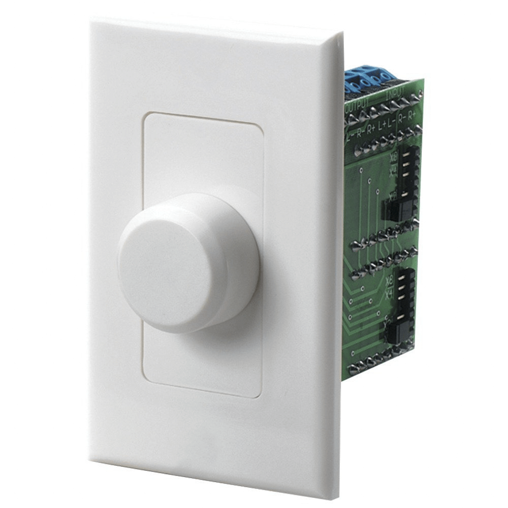
Sometimes it is not convenient to have to go to the lounge room to control the volume of the speakers – especially if you are some distance away and the phone starts to ring. Therefore it can be useful to have a volume control in each zone (area) where there are speakers. This way, the volume for the speakers for the workshop is controlled in the workshop. The disadvantage of this is if you leave the volume control up (say for the outside speakers) and the next morning you play music without going outside – you will be entertaining the neighbours with your music in the morning as well as the night before.
In-wall volume controls are similar to the volume controls mentioned above – they come with impedance matching or without impedance matching. For more than one pair of speakers you would normally want impedance matching. If you are having two zones (two pairs of speakers or four speakers) then you will select the x2 on the back of the impedance matching volume control. Similarly, if you are using 3 or 4 pairs of speakers, you will select x4.
Bear in mind that these are mostly “in-wall” controls. If you need to mount them on a solid brick or concrete wall, you will need a big mounting block, or a deep recess in the wall. The transformers on these volume controls are normally deeper than a standard mounting block for solid walls. The greater the power handling ability of the volume controls, the larger the recess required (and the more expensive the control).
Wiring these volume controls is fairly simple. Run a speaker cable (probably two, one for left side and one right side) from the amplifier to the volume control. Then run a speaker cable from the volume control to each speaker.
Remember to allow a volume control for the lounge room speakers so they can be controlled also.
You can use this method for 2 speakers, 4 speakers or more.
Practical Considerations in Wiring Four Speakers
The above installations will work, but they have some limitations. The biggest limitation is the volume control on the amplifier. This controls the maximum volume to all four speakers. The individual volume controls for each speaker only reduce the level coming from the amplifier – they can’t make the sound louder than what the amplifier produces. This means the amplifier volume control needs to be set at the level of maximum volume you want for any given speaker. However it is not wise to set it at full volume. You don’t want the amplifier running flat out but all the speakers turned way down (this is like revving the car engine at maximum and then only letting the clutch out a little bit) – far better to run the amplifier only to the maximum required.
The best method for setting up a system with speaker volume controls is:
- turn all the speaker volume controls all the way up
- gradually increase the volume control of the amplifier until the music is just louder that you would normally want it.
- This is the position for the amplifier volume control.
- you can now turn each speaker down a few steps to the level you want.
The above method will work fine until someone uses the remote control and changes the volume. This will happen regularly if you watch movies or TV and listen to the sound through your HiFi amplifier/speakers. One solution is to hide the remote control – but this isn’t always convenient. There is a better solution, but you may not need it.
The installations above with the speaker selector switch, or with the volume controls suit a number of situations. They are very suitable when you want the same music (from an MP3 player or media centre) available throughout the house and you don’t touch the amplifier. I have installed many of these systems in houses where the amplifier is only turned on in the morning and turned off at night. Sometimes the amplifier is installed in a ventilated cupboard so it is never seen nor touched. This allows the household to move around the house listening the same music in every room.
However if your amplifier is used while watching TV or movies and the volume is constantly being adjusted with the remote control, then the other speakers in house will also be adjusted accordingly. The easiest way to solve this problem is with a second amplifier. This is my preferred method. Connect the line out of the main amplifier into the “slave” amplifier. This way, the program is the same in every room, but the HiFi amplifier volume can be changed as much as you like, without affecting the other speakers. The volume on the slave amplifier can be set (as outlined above) and then never touched.
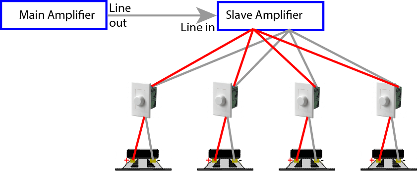
The slave amplifier can be a second hand amplifier, an old “stereo”, or a new stereo amplifier. Some HiFi (main) amplifiers have a power socket at the back to allow other equipment to be connected. If this is the case, then plug the slave amplifier in to this power socket and it will be turned on and off with the main amplifier.
In Closing…
I hope this has helped you understand how-to, and how-not-to, wire four (or more) pairs of HiFi speakers around your house. The video in the article Understanding Speaker Impedance explains how each of the different types of Speaker Selector Switches provides impedance protection or impedance matching. Also my Speaker Selector Switch Simulator provides an interactive way to see how they treat impedance and power sharing.
For a practical discussion on how to wire just 2 speakers to an amplifier (4 speakers to a stereo amp), see my article on How to connect 2 speakers to 1 amplifier.
If you need to wire more than four speakers, particularly in a commercial installation, see the article on Distributed Speaker Systems.
Keep in mind that changing the total load impedance of an amplifier will increase or decrease the power output of the amplifier. See Multiple Speakers Change Amplifier Power for more details. Also different speakers may sound louder or softer than others due to there sensitivity – see Understanding Speaker Sensitivity for a better understanding.
Also if the speakers each have a different impedance, then there will be different power levels available to each speaker. For more detail see How Multiple Speakers Share Power.
Many practical examples of the methods outlined above have been explored in the comments below.


 Calculation of output current (I):
 So, from the specifications and a couple of calculations, we now know the following:Power=100 watts Impedance (resistance) = 4 ohms Voltage = 20 volts Current = 5 ampsAn equivalent circuit will help us visualise what is happening.


 In practice, because the speaker impedance is increased, the load is decreased and the amplifier is capable of outputting around 23 volts which gives a maximum power output of 70 watt @ 8 ohms.The important principal is: the higher the speaker impedance, the less current required from the amplifier. Also, the lower the speaker impedance, the more current required from the amplifier.OK, this is all very good, but what about connecting two or more speakers to the amplifier? Glad you ask, this is the fun bit. Let’s connect two 8 ohm speakers to the one amplifier.


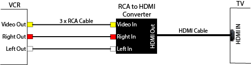
 and the reverse, a HDMI to RCA converter. To connect a VCR to a TV using HDMI, you need a RCA to HDMI converter.


 so
so 


 .
.