Amplifier, Speaker & SPL Calculator

40

These calculators will find how loud an amplifier and speaker combination will be, or what size amplifier you need to make a speaker a certain loudness.

There are five factors which contribute to how loud a speaker will be:

1) The distance from the speaker. Sound drops off the further you are away from a speaker.

2) The SPL required. This is how loud you want the sound to be at the distance specified. Some general levels are:

  • 70-80dB  for speech only
  • 80-95dB for light music
  • 95-110dB for heavy music

3) The speaker sensitivity. This is not an indicator of how sensitive the main (human) speaker is, but rather a measurement of the sensitivity of the loudspeaker. It should be available in the specifications for the loudspeaker (see Understanding Speaker Sensitivity for more info).  It is normally stated as the SPL measured 1 metre in front of the speaker with 1 watt of power driving the speaker. Hence the specification will read something like:

Sensitivity (1W/1m) = 85dB

4) Amplifier headroom. This is an allowance for the amplifier to cope with peaks without distortion. At least 3dB headroom is generally recommended. Note that for every 3dB allowance, the power requirement doubles.

5) The power of the amplifier, measured in watts.

In the calculator below, first input the distance from the speaker (and select feet or meters). From this distance the Sound Pressure Level (SPL) loss over that distance is calculated in decibels (dB).

Then, fill in the input fields of either calculator depending on if you want to know the required power for a target SPL (use the first calculator), or if you want to know how loud a given amplifier will be (use the second calculator).

Note: the calculator is best viewed in landscape mode on phones and small screens

Download Calculator
as Excel File
Prices in US$

Note: these calculations are for “open-air” where there are no reflections from walls, ceiling and/or floors. When reflections are present, the SPL losses can be reduced by up to 6dB.

For those who need to know, the formulas used for these calculations are:

\large{SPL\ loss = {20\times Log_{10}\left(\frac{Distance\, from\, Spkr\left(meters\right)}{1}\right)}

and

\large{ Amplifier\ power =  \large{10^\frac{required\,amp\,gain}{10}}

Speaker Impedance Changes Amplifier Power

Speaker impedance changes amplifier power output. In fact, your amplifier power could be nearly half or double its capacity – depending on the impedance of your speakers. But how much should this concern you?

Impedance is measured in ohms. The Omega symbol (Ω) is used for shorthand.

Amplifier Output Power

Let’s say we have an amplifier. The specifications might say the output power is 100 watts RMS at 8 ohms.

Notice the power output (100 watts) is at a specified load (8 ohms). This is telling us that with an 8 ohm speaker, the maximum output power will be 100 watts.

An Ideal Amplifier

If our sample amplifier were an ideal amplifier, then we can also calculate¹ that:

  • With a 4 ohm speaker, the maximum output power will be 200 watts.
  • With a 16 ohm speaker, the maximum output power will be 50 watts.

The above shows that for an ideal amp, halving the impedance doubles the power output. Doubling the impedance halves the power output.

Halving speaker impedance doubles amplifier power.

Doubling speaker impedance halves output power.

An ideal amplifier is an amplifier which is theoretically perfect. Of course, such an amplifier does not exist, but they are useful when explaining how speaker impedance changes amplifier power.

You can use the following calculator to determine the possible power output with different impedance speakers. Simply type in the power rating of your amplifier and the specified impedance (ohms) – Eg, 80 watts @ 6 Ω.

¹All these calculations use standard electrical formulas which you can read more about in the articles What is Electrical Power, and The Dreaded Ohms Law.
 

In summary, in an ideal amplifier, the current from the amplifier will depend on the speaker impedance (ohms). The lower the speaker impedance (in ohms) the greater the current that can be drawn from the amp, which means the greater the power.

Real World Amplifiers

The above calculations work well for an ideal amplifier, and help show how speaker impedance changes amplifier power output.

In reality, amplifiers cannot maintain the theoretical output levels as calculated above. This is because the power supply on most amplifiers cannot maintain the maximum power when driving the lower impedance speakers.

In a real amplifier, the above principles still hold but the theoretical values will not be achieved. The power output will be increased with lower impedance speakers, but the maximum power output will not be doubled when the impedance is halved.

As an example of a real world amplifier, let’s look at the specifications of a popular PA Amplifier purchased at Amazon through this site, the Crown XLS1000.

XLS1000 specs - speaker impedance changes amplifier power

This shows that for this amplifier, with both (dual) channels used at the same time, the maximum power output of the amplifier changes as the speaker impedance changes:

  • With an 8 ohm speaker, the maximum output power will be 215 watts.
  • With a 4 ohm speaker, the maximum output power will be 350 watts.
  • With a 2 ohm speaker, the maximum output power will be 550 watts.

This example shows that in a real world amplifier, the principle of “speaker impedance changes amplifier power output” is true, just not as much as in an ideal amplifier.

Please note: this amplifier is designed to work with a speaker impedance as low as 2 ohms. Most HiFi amps are only designed to work with a speaker impedance of (or above) 4 ohms.

So What?

So what should you do with this marvelous knowledge? If 4 ohm speakers gives you nearly double the power of 8 ohm speakers, should you only use 4 ohm speakers?

Answer: Yes, and No.

4 ohm speakers are used widely in the car audio industry, as they want to squeeze every bit of power capable from a fixed voltage (~12-14 volts from a car battery). They also mostly design and build their amplifiers to cope with 4 ohms and often 2 ohm loads.

However, it may not be wise to run your Hifi amp flat out at 4 ohms. The reason being, it may mean you are running your amp at or beyond its design limits. The cheaper the amp, the closer you are likely to be at the limits of the power the power supply can cope with. Better to use 6 ohm or 8 ohm speakers, and let your amp comfortably drive them without reaching full capacity. This is similar to a car: better not to constantly drive with the motor at full revs. Interestingly, most Hifi speakers are 6Ω or 8Ω.

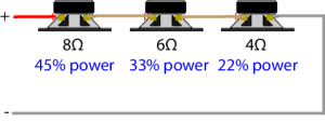
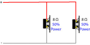
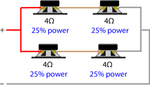
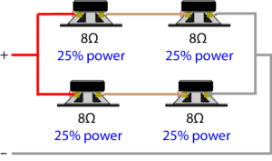
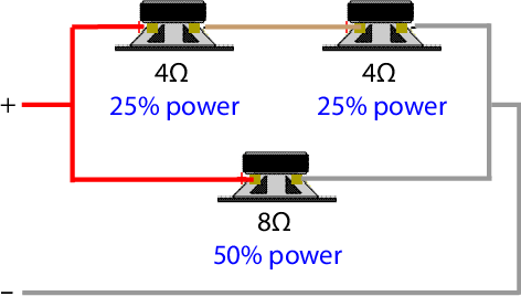
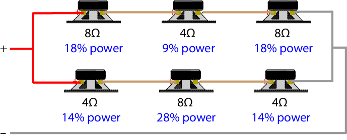
A common method of changing speaker impedance is by adding another speaker, either in series or in parallel with the existing speaker. While this will change the output power of the amp, the speakers will share that power. For more details see How Multiple Speakers Share Power.

Most modern amplifiers will, if they are overloaded,  either turn themselves off or reduce the output to protect themselves. However, it is wise not to rely on this self-preservation circuitry, best to design your system conservatively.

Keep in mind that all this is describing the maximum power output of an amplifier. If you don’t run your amp anywhere near full volume, then all this is fairly much irrelevant.

Also keep in mind that doubling the amplifier power only increases the volume by around 23%.  To double the volume you need around ten times the power. For an explanation of this, see the article on Double Amplifier Power does not Double the Volume. 

If you need maximum level from your speakers, pay attention to the sensitivity in the specifications. Using a speaker with a sensitivity of 90dB (1W/1m) compared to another speaker rated at 87dB (1W/1m) is the same as doubling the amplifier power driving the speaker. For more details on this see the article Understanding Speaker Sensitivity.

While speaker impedance changes amplifier power output, it is not a major consideration for most users. It only becomes relevant when running your amplifier at full power, and then it is best not to run it too close to its design limits.

Never use a speaker (or speakers) below the minimum impedance the amplifier is designed for. If you hear any distortion, it is an indication that major trouble is just around the corner – turn the volume down, eliminate the distortion and consider a redesign of the system.

If you have a question, please read the FAQs before submitting your question.

Connecting Speakers FAQs

After answering nearly 1000 questions on connecting speakers on this website, some common themes have emerged.

Please read the answers to these Frequently Asked Questions (FAQs) on connecting speakers before asking your own.

If you have 2 speakers wired in series, then simply add their individual impedance together. For example: A 4 ohm speaker in series with a 8 ohms speaker: 4 + 8 = 12 ohms.If you have 2 or more speakers in parallel and all the speakers are the same impedance, then divide that impedance by the number of speakers. For example: if you have three 8 ohm speakers, then 8 ÷ 3 = 2.67 ohms.If you have 2 or more speakers in parallel and all the speakers are not the same impedance, then it is easier to use my Speakers in Parallel Calculator.Note: all these calculations are for connecting manufactured speakers (boxes). They are not used when building your own speaker box and connecting multiple speakers in a cabinet using a crossover circuit. A crossover splits the signal into different frequencies for each of the speakers and makes the total impedance calculation complex (as impedance is frequency dependent). That is why speaker designers get the big money, and as installers we benefit from their expertise. 

Most Hi-Fi amps require a minimum load impedance of 4 ohms or 6 ohms.

Two 6 ohm speakers in parallel gives a total load impedance of 3 ohms. This is below the minimum of 4 or 6 ohms, therefore it is not advisable to connect two 6 ohm speakers in parallel directly to a Hi-Fi amp.

You can use a 2 zone speaker selector switch which uses a series resistor. This will add a series resistor of 3-5 ohms (depending on the manufacturer.) Therefore the 3 ohms (of the two speakers in parallel) and the series resistor (of the selector switch) will bring the total load impedance above 6 ohms, so all should be good for the amp.  However the resistor will reduce the power available to each speaker (by up to 60%).  See my speaker selector simulator for more details.

You can also simply connect both speakers in series. This will bring the total load impedance to 12 ohms, which will be fine for the amp as it above its minimum load impedance. However, the maximum power of the amplifier will be slightly reduced. For more practical details see my article on How to connect 2 speakers in series.

For more examples of connecting multiple speakers to a HiFi amp see my article on Understanding Speaker Impedance. The video in this article also describes how the different types of speaker selector switches help with impedance.


Generally no, but with some speakers you can.

Many Hi-Fi stereo amplifiers have connections for Speaker A and Speaker B. These connections are **normally in parallel, so it is the same as connecting two speakers in parallel – but the amp provides switches to turn each set on or off.

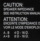
These are designed to allow easy connections of 2 sets of speakers. Normally these amp have a warning notice. This notice is saying that when connecting to either A or B, then the speaker should have an impedance of 4-16 ohms. But when connecting to both A+B, then each individual speaker should be 8-16 ohms.

So if you have 2 sets of your speakers which are 8 ohms or more, then you can safely use these connections.  This is because two 8 ohm speakers in parallel gives a total impedance of 4 ohms – the minimum impedance the amp is designed for.

However if your are connecting speakers with an impedance less than 8 ohms, or you have more than 2 sets of speakers, then you should not use these connections as the total impedance will be below the minimum 4 ohms.

For these speakers you could connect them in series to Speaker A only. Or you can use a speaker selector switch connected to Speaker A only.

** Most amplifiers with an A/B switch connect both outputs in parallel, but there are the occasional exception where they connect both outputs in series.


When more one than one speaker is connected to an individual amplifier, they can be wired in series, parallel or (rarely) in series/parallel.

Speakers in Series

Two or more speakers can be wired in series. That is, one wire is used to to go from each speaker to the next. 4 speakers in seriesThis is not normally used for more than 2 speakers. For a practical discussion on wiring 2 speakers in series, see the article on Connecting 2 speakers to an amplifier. 

To calculate the total impedance of speakers in series simply add the impedance of all the speakers together. For example, in the diagram above, if each speaker was 4 ohms, then the total load impedance seen by the amp would be 4 + 4 + 4 + 4 = 16 ohms.

Adding speakers in series is a safe way of adding speakers to an amplifier, but not always practical. The higher total impedance also doesn’t allow the amplifier to produce its maximum power. For more in how impedance changes amplifier power, see the article on How impedance changes amplifier power.

Speakers in Parallel

Two or more speakers can be wired in parallel. That is, two wires are used to connected from one speaker to the next.

4 speakers in parallel schema

This is the easiest and most common way of connecting 2 or more speakers. Wiring each speaker back to the amplifier with separate wires is also wiring them in parallel.

4 speakers in parallel at ampBoth of the above diagrams show 4 speakers wired in parallel. If you follow each wire with your finger on the lower diagram you will see it is effectively wired the same as the first diagram.

Due to the total impedance, it is rare you can wire more than 2 speakers in parallel.

If each speaker is the same impedance, it is easy to calculate the total load impedance of speakers in parallel. Simply divide the individual speaker impedance by the number of speakers. For example, in the above diagrams, if each speaker is 8 ohms, then the total load impedance would be 8 divided by 4, which equals 2 ohms.

If each speaker has a different impedance, then it is is easier to use my Speaker in Parallel calculator.

Wiring 2 speakers in parallel is very common in domestic and commercial installs. You just need to ensure the total load impedance of the speakers in parallel is above the minimum impedance required by the amplifier.

If you need to wire more than 2 speakers in a domestic install, you can use a speaker selector switch if the total load impedance is below the amplifier’s requirements.  For more details on wiring 4 or more speakers to an amplifier see the articles Connecting 4 speakers to an Amplifier, Speaker Selector Switch summary, and my unique Speaker Selector Switch Simulator.

If you need to wire more than 2 speakers in a commercial install, there are three alternatives. Firstly you can get commercial amplifiers designed to work with a load impedance as low as 2 ohms. Secondly, you can use multiple amps, That is, one dual channel amp for every pair or for every 2 pairs of speakers. Thirdly, you can use a distributed speaker system.

Impedance is a characteristic of a speaker you need to take note of, especially if connecting more than one speaker to an individual amp. See the article on Understanding Speaker Impedance for details.

The first important point to note is you should not connect a speaker combination with a total impedance lower than the minimum the amp is designed for.

For example, if your amp says the speakers should be 4-16 ohms, then connecting a 4 ohm, or 6 ohm or a 8 ohm speaker is fine. But connecting two 4 ohm speakers in parallel (which results in 2 ohms total load impedance) is too low. To  calculate the total impedance of speakers in parallel see the popular Speaker in Parallel Calculator.

If you do connect a total load impedance which is lower than the amp’s minimum, you run the risk of overloading the amp; causing it to turn off, blow a fuse or blow the electronics. You can get away with a lower impedance at low volume levels, but as the amp gets close to its full output, it will get hot and stop working.

The second important point to note is you normally can have a total load impedance above the recommended maximum (Eg above 16 ohms). However the higher the load impedance, the less power the amp will be able to produce. See the article on Speaker Impedance Changes Amplifier Power.

Some amplifiers will detect that the impedance is too high and turn off thinking there is no speaker connected, but most amps will have no problem.

The exception is a tube (valve) amp. Most tube amps require some load and don’t like having no load.


In a perfect world, every cable should be labelled, identifying which speaker they are connected to. However, that is often not the case. Perhaps you are helping a friend, or you have moved into a new house which has speakers in many rooms, or perhaps the kids have pulled the wires out for fun. Whatever the reason, you’ll be pleased to know there is a cheap and easy way to find what speaker each cable is connected to.

You will need two things: someone to help you, and a 1.5 volt battery.

Each cable going to a speaker has 2 wires. Make sure the wires are stripped (that is, the outer plastic is stripped off, allowing around 12mm (1/2″) of bare copper wire to be seen at the ends.

Hold one of the wires (doesn’t matter which one) on the bottom of the battery. With the other wire, tap it on and off the top of the battery (the +ve terminal). The connected speaker will make a scratching noise. Note: the speaker only makes a noise when the wire is tapped on or off the battery. So keep tapping the wire on and off the battery until your assistant finds the speaker which is making the noise.

Once identified, label the speaker cable.

Other Methods

Use an impedance meter: an impedance meter sends a tone (normally 1kHz) down the cable to measure the speaker impedance. Most meters also allow the tone to be held on continuously so you can test and/or identify what speakers are connected. This is a great way as the meter will also tell you the total load impedance.

Connect to amplifier: You can connect the cable under test to an amplifier playing some music at a low volume level. Just be careful not to short the wires when connecting the amplifier. Probably best to turn amp off when making each connection.

You can certainly design your speaker boxes, but I wouldn’t.

I’m an installer, not a speaker designer. I’ve installed many speakers, but I wouldn’t like to try to design them. The internals of a speaker box (cabinet) is complex.

The simple calculation of speakers in parallel is only useful if your don’t use a cross-over circuit (a circuit which splits the signal into different frequencies to best match each speaker in the box).

The complexity of the total impedance of a speaker (box) is not the only issue. Other things I’m aware of (among other issues) that need consideration are:

  • The internal volume of the cabinet (less the volume of the other speakers) needs to match the characteristics of the biggest speaker
  • The effect of the air movement caused by one speaker might have on the other speakers
  • The matching of the crossover circuit to each of the speakers
  • The phasing of each speaker relative to the other speakers
  • The overall flatness of the resultant frequency response.
  • The power handling of each speaker

So, I leave all that to the people who get paid the big bucks to design speakers. We need to simply install and enjoy the product of their effort.

It is not possible to make two 8 ohm speakers into a 8 ohm load.

There are only two ways to connect two speakers together, either in series or parallel.

In parallel, two 8 ohms speakers give a total load impedance of 4 ohms – too low for any amp designed for a minimum load of 8 ohms.

In series, two 8 ohm speakers gives a total load impedance of 16 ohms. This will work with amps designed for a minimum load of 8 ohms. However the amp will not operate at full power. In a domestic install, a simple series/parallel speaker selector switch can be used to do this, as well as enable any one pair of speakers to be connected on their own. However, with a 16 ohm load, the amplifier’s output power will be reduced by 3dB compared to using just one 8 ohm speaker.  For more info on this see the article on how Speaker impedance changes amplifier power. 

For the best power output, you would be better off to use just one 8 ohm speaker, provided it will cope with the full amplifier power.

So, it comes down to what you are trying to do. If you want maximum power, then use just one speaker. If you want a wider area covered than what one speaker will cover, then use the two speakers in series.

Also if maximum power is not an issue, then you could also use a speaker selector switch with a series resistor. This will add a 3-5 ohm* resistor in series with the speaker. This will allow both speakers to be wired in parallel (4 ohms total load impedance) in series with the resistor (3-5 ohms) to give a total load impedance close to 8 ohms. However the resistor will take close to half the power of the amplifier.  This is not normally a problem when using multiple speakers in a house, but not so good in a commercial installation requiring maximum power.

*the value of the resistor depends on the manufacturers design.

To see how much power a speaker selector switch resistor takes, see my simulator here.

For a more a detailed understating of speaker impedance, see the article on Understanding speaker impedance.

For more on how to wire speakers in series or parallel, see the article on Connecting 2 speakers to 1 amplifier.


If, after reading these FAQs, you still have a question, please ask it in the “comment” box below.

In your question, please include as many details as you can. Include the make and model of the amplifier and speakers as I often try to find the specifications and/or manual for your equipment to better answer your question.

I also ask for your location. This is helpful as some countries have different policies and practices. It also helps me suggest any products and suppliers available to you if you need some extra equipment.

It takes a lot of my spare time answering readers’ questions, so I filter some questions. I may not answer questions, or only give a brief answer if your question is

  • Already answered in these FAQs
  • Already answered in my other articles (I expect you to have tried to find a solution yourself)
  • Off topic.

I trust you can appreciate I only apply these filters to allow me to concentrate on answering those question not already covered.

Other articles which might help you include:

Welcome

    0

    This site is dedicated to helping you understand and use your technology.

    It is not a site about the latest electronic gadget, nor is it just a “how to” website. Most articles provide a balance of practical tips and explanations. There are also reference articles where you can learn and understand more about the principles behind connecting and using your technical equipment. Understanding the technology will make it easier to work with it, rather than being frustrated by it – or at least, you will understand why you are frustrated with it.

    The articles are grouped into major interest areas. Please browse the section(s) which may be the most helpful to you.

    [vc_cta h2=”Home AV” txt_align=”center” style=”3d” color=”white” add_button=”bottom” btn_title=”View Home AV Articles” btn_color=”primary” btn_align=”center” btn_css_animation=”appear” css_animation=”left-to-right” btn_link=”url:http%3A%2F%2Fgeoffthegreygeek.com%2Fcategory%2Fhome-av%2F||” css=”.vc_custom_1460069339635{background-color: #ffedce !important;}” btn_button_block=”true”]Articles about connecting your home entertainment system(s). “Connecting Speakers” has articles on the various ways of adding extra speakers to your sound system. “Connecting Equipment” includes articles on how to connect a VCR, Wii and a PVR to your flat screen TV.  The articles are general in nature and do not push any particular brand. Each articles tries to include practical tips and a technical explanation.[/vc_cta]
    [vc_cta h2=”Understanding Audio” txt_align=”center” style=”3d” color=”white” add_button=”bottom” btn_title=”View Understanding Audio Articles” btn_color=”primary” btn_align=”center” btn_css_animation=”appear” css_animation=”right-to-left” btn_link=”url:http%3A%2F%2Fgeoffthegreygeek.com%2Fcategory%2Funderstanding-audio%2F||” css=”.vc_custom_1452924751599{background-color: #ffedce !important;}” btn_button_block=”true”]Articles to help you understand “audio”. This is designed for people wanting to learn about setting up audio systems, or understand more about getting good audio from a PA system. It is written for intelligent novices: particularly teachers, leaders, musicians and students who need to understand their sound system at school, church or group.  It is also useful for PA operators, journalists, videographers and even technicians.[/vc_cta]
    [vc_cta h2=”Fundamentals” txt_align=”center” style=”3d” color=”white” add_button=”bottom” btn_title=”View Fundamental Articles” btn_color=”primary” btn_align=”center” btn_css_animation=”appear” css_animation=”left-to-right” btn_link=”url:http%3A%2F%2Fgeoffthegreygeek.com%2Fcategory%2Fur-the-technician%2F||” css=”.vc_custom_1452924773142{background-color: #ffedce !important;}” btn_button_block=”true”]Articles designed to help you understand some technical basics, including simple explanations of fundamental principles & formulas, as well as how to use a multi-meter.[/vc_cta]
    [vc_cta h2=”Calculators” txt_align=”center” style=”3d” color=”white” add_button=”bottom” btn_title=”View Calculators” btn_color=”primary” btn_align=”center” btn_css_animation=”appear” css_animation=”appear” btn_link=”url:http%3A%2F%2Fgeoffthegreygeek.com%2Fcategory%2Fcalculators%2F||” css=”.vc_custom_1452920217314{background-color: #ffedce !important;}” btn_button_block=”true”]A collection of simple calculators to help you better understand and use the audio and electrical principles outlined in the articles of this web site. You may like to bookmark these.[/vc_cta]
    [vc_cta h2=”Myths and Trivia” txt_align=”center” style=”3d” color=”white” add_button=”bottom” btn_title=”View Myths and Trivia” btn_color=”primary” btn_align=”center” btn_css_animation=”appear” css_animation=”right-to-left” btn_link=”url:http%3A%2F%2Fgeoffthegreygeek.com%2Fcategory%2Fmyths-trivia%2F||” css=”.vc_custom_1452815459976{background-color: #ffedce !important;}” btn_button_block=”true”]A fun section that looks at some of the technical myths that are often mis-understood and some short bits of technical trivia which I find interesting – let me know if you do too.[/vc_cta]

    I hope you find the information in these articles useful. If you do, please let others know about this resource – you can even click on the Facebook “like” button here. To save you checking in to see what is new, simply leave your first name and email address in the “Newsletter” box (located lower right) and I will let you know every now again about new articles.

    “Understanding is a fountain of life to the one who has it, but stubborn fools punish themselves with their stupidity”Proverbs 16:22 GOD’S WORD® Translation (©1995)