In this article, we look at composite video signal: what it is, what cables to use, where composite video is used and the problems with it. This is the first in a series of articles outlining the different video signals used in home entertainment for connecting VCRs, DVDs, set top boxes, cameras and laptops to TVs and projectors.
What is Composite Video?
As the name suggests, composite video is “composed” of everything required to make up a TV picture. It has the basic black & white picture information (luminance or luma), along with the colour information (chrominance or chroma) as well as the timing information (sync). It is the most basic (and simplest) form of video signal.
Cables to use for Composite Video
You are probably aware of the yellow, red and white connecting leads. The yellow one is generally used for composite video (the red and white ones are used for left and right sound). The plugs on each end are called RCA plugs, and these leads are normally called RCA leads, or AV leads (audio and video). These leads are good for short distances up to 5 metres (15 feet). For longer distances (to connect to a projector), thicker cable should be used for composite video signals. This larger cable is normally called RG59. It can be used for distances up to 100 metres. You can buy pre-made RG59 video cables in 5, 10, 15 and 20 metre lengths. For longer lengths, the cable is normally installed and then the connectors attached (soldered or crimped).
RCA comes from the company Radio Corporation of America. RCA originally used these plugs to connect phonographs (record player) to radio/amplifiers. Hence RCA plugs are also known as phono plugs.
Where Composite Video is used
Composite Video is used mostly for Standard Definition TV, and not for High Definition. Composite Video was used extensively in Video Cassette Recorders (VCRs) to connect to TVs. The familiar yellow RCA lead is simply connected from the yellow “Video Out” socket on the VCR to the yellow “Video In” at the back of the TV. Generally the red and white audio leads are connected to their respective coloured sockets for the audio. Longer video cables are also connected between a VCR and a projector.
As Composite Video is a basic video signal that all TVs and projectors can use, the familiar yellow “Video Out” socket is still available on DVD players and Set Top Boxes so that older TVs can still be connected to them.
Problems with Composite Video
A TV or projector needs to separate the various bits of picture information (luma, chroma and sync) in order to re-create the picture, and this is the problem with composite video. It is impossible to separate all the information back to the original quality once it has been mixed together in the one cable. This means the picture is not as crisp and the colours not as defined as they could be.
Asking which flat screen TV to buy is similar to asking which car to buy. There are many choices, but at the end of the day they all show a picture, like all cars get you from A to B. This article will help you understand what to look for in a flat screen TV which suits your circumstances. For many people, the first decision is LCD or Plasma. I believe this is a minor decision. Most people can’t tell the difference between the two, so I suggest it really isn’t a major issue. It is a consideration though, so the differences will be discussed latter. The more important issues are the size of the flat screen TV and the connectivity.
What Size Flat Screen?
Ask this question on the internet and you get confused very quickly. The answers normally recommend multiplying the screen width, or screen height, or screen diagonal by a figure to determine the optimal distance to watch the screen from. Interestingly, most websites selling flat screen TVs tend to suggest very big (and more expensive) flat screens. Home theatre websites suggest sitting relatively close to the screen to replicate the “immersive” experience of a cinema. The question is, do you want/need to be that immersed in your normal TV viewing? “Bigger is Best” is a great sales line, and one normally swallowed hook, line and sinker by males. However, the biggest may not be the best – especially for the budget. That said, given all other things are equal, when comparing two screens, going to the bigger one may be better than choosing the smaller one. This is because most screens will look big compared to your existing screen, but in a few months time you will be used to the new larger screen, and may regret not getting the bigger size.
Be Practical
There are a number of practical considerations when determining what size flat screen TV to buy. Firstly, what physical space does the screen have to fit. Most flat screens don’t easily fit into the space designed for an older CRT TV in an entertainment unit. A bigger screen may involve modifying or buying a new stand/cupboard/entertainment unit. Measure and note the space the new screen needs to fit into. Secondly, measure the distance from your normal seating position to the where the screen will be. Now go to a store, and stand that distance away from one of the screens. Ask yourself the following questions: – Can you read the graphics on a news program or sporting event? If not, you need a bigger screen? – Can you see the pixels (the little dots that make up the picture?) If you can, you need a smaller screen. – When watching a fast moving program (sports or action), does the motion look blurred or fuzzy? If so, look at the same program on a smaller screen. – While watching an action film do you feel nauseous like you are watching a film too close to the screen in the cinema? If you do, the screen is too large. Keep looking at different size screens until you find the size(s) that you are comfortable to watch at your normal viewing distance, and which will fit in the space you have for it. Note: this exercise is to determine the size only, there are other considerations to think about before you decide on which TV to chose.
What connections do you need?
It is important to ensure that any flat screen TV you buy is going to be able to connect to any other AV equipment you have or may have during the life of the TV. Most new devices will connect to the new flat screen by HDMI. These devices include Personal Video Recorders (PVR – like a VCR but uses a hard disk instead of a tape), HD satellite or cable boxes, Blue Ray DVD players, games consoles and newer DVD players. You may not have these now, but you may in the next 5-10 years, so having 3 or 4 HDMI sockets is a good idea. Most new flat screen TVs will have this. Older DVD players and satellite boxes should be connected with the red, green and blue component video cables. Most flat screen TVs have 2 or 3 component video inputs. If you have a VCR that still works and you want to watch videos, you are going to need an AV input. This is called composite video and audio, and uses the yellow, red and white connectors. Be aware, many new flat screen TVs do not have a direct connection for composite video. Some are allowing the yellow composite video signal to plug into the green ‘Y’ socket of the component video input. Make sure you check the new screen has some ability to input composite video if you still need to watch the output of a VCR.
Sound
If you want the sound from the TV to be connected to your HiFi amplifier, you will probably also need to have an audio out. This is not always available on new flat screen TVs. There is generally a digital audio out, and this can be connected to some modern HiFI or surround sound systems. Older amplifiers need an analogue audio out, which connect using the common red and white RCA or phono leads. If the flat screen TV you really like doesn’t have an audio out, it is possible to purchase a separate little convertor box which will convert the digital audio out from the screen to the analogue audio your older amplifier requires.
Updated June 2013: As manufactures are making the screens as thin as possible, it is becoming increasingly more difficult for them to fit decent size speakers in. This results in many flat screen TV’s having sound which is “tinny” or “thin” or “sounds like a toy”. It is difficult to make these speakers sound better, so try to listen to the sound before purchasing a flat screen TV.
If the sound quality is poor, the best way to improve it is to connect to an external amplifier/speaker system. This may be an existing amplifer and speakers or a unit designed to improve the sound of flat screen TVs.
There are many 3rd party vendors selling speakers which will clip on the sides of your new flat screen TV or sit in front of or under the screen. The ones that sit in front are called “sound bars”. Sound bars come in different shapes and sizes (and different prices). Some include a sub woofer, some have a left, centre and right speaker incorporated, while others may just have a left and right speaker. They offer a simple one connection solution to poor speakers.
If you are interested in purchasing a sound bar to improve the sound quality, here is a link to Amazon’s range of sound bars from USA or UK or Australia. Disclosure: If you buy through these Amazon links Geoff receives a small commission from each sale.
While these work work well, you may not to do buy something extra for your new flat screen TV, so take my advice and try to check out the sound before you purchase. This is especially important if you are buying a small size TV. Small flat screen TVs are particularly prone to poor sound.
What other features do you need?
If you only want to watch TV, then you don’t need all the features that are often packaged with the higher end flat screen TVs. Some of the features often included (in the price) are:
3D: some DVDs and TV broadcasts feature various forms of a simulated three dimensional picture. All 3D screens require special glasses to watch the 3D. All 3D screens also show 2D pictures without having to use glasses.
Internet: Most flat screen TVs also have a connection point for an internet cable (and a wireless connection). These “Smart TVs” allow you to use your TV for Skype calls or stream programs using Netflix, Stan, Amazon Prime, YouTube etc. Note: you have to subscribe and pay for some of these services.
USB: Most flat screen TVs now have a USB port which allows you to view photos or videos directly from a USB memory stick.
If this technical talk sounds like gobbly gook, then you don’t need to worry about these features. More importantly, try to get a flat screen TV which doesn’t have these features. However, it appears most manufactures are heading towards making these features standard.
What are you waiting for?
OK, you know what size flat screen TV fits your situation. You know what connections you need your new flat screen TV to have. You know what features you want or don’t need. So go for it. Go visit to a few shops and look at all the flat screen TVs of the size you want. Most stores have special deals, so see if you can find a good deal for a flat screen TV that meets your requirements. Beware of very bright and colourful screens. Many retailers turn the colour up to make the picture look better. If you can, ask the sales person to turn the colour down so the skin tones are natural and not too orange. Then compare the picture of the ones that meet your criteria and are a good deal.
What brand TV?
Like cars, there are many manufactures of flat screen TVs. Like cars, there are well established brands and new Asian manufactures coming on the scene. Like cars, there is a range of models within each brand, targeting different markets and budgets. Like cars, some brands have loyal followers, and some people just want the best value for money at the time of purchase. Like cars, the choice is yours.
What about Plasma, LCD or LED?
There are different methods of producing a picture, but the resulting picture is similar whichever way it is produced. There are pros and cons of each method, but the differences between them are getting smaller. Similar to cars: you can have a petrol or diesel engine, there are pros and cons for each, but the differences are getting smaller, and seeing them on the road, it is difficult tell any difference.
Plasma Flat Screens
Plasma flat screens use very small cells of gas for each pixel. As an electric charge is applied to the cell, the gas turns into plasma which makes some phosphors emit a controlled light. Plasma screens are normally 42″or larger.
LCD Flat Screen
LCD flat screens use very small crystals for each pixel. As an electric charge is applied to the crystal, it acts like a shutter allowing various amounts of light to shine through it. Therefore it requires a light behind the panel. On standard LCD screens the lights are compact fluorescent tubes. LCD screens go from 17″ to 80″. LCD screens above 40″ are mostly LED LCD flat screen now.
LED Flat Screens
So called LED flat screens are simply LCD screens which use LEDs (light emitting diodes) instead of compact fluorescent tubes as the light source. LEDs are smaller and more efficient. By moving them to the edge of the screens and using light guides to direct the light to behind the pixels, manufactures have been able make very thin screens. LED flat screens should be called LED LCDs, or LCDs with LED backlight.
LCD or Plasma Flat Screen TV
The above tells you the very simple technical differences, but what about in practice, what are the differences? The following table outlines the differences and similarities.
Attribute
Plasma Flat Screens
LCD Flat Screens
Comments
Picture quality
Very good. Often preferred for movies
Very good
Both produce very watchable pictures
Off-centre viewing (viewing angle)
Very good
Originally poor, now very good
LCDs now have a very wide viewing angle
Ability to display fast action
Very good
Originally poor, now good
most people cannot see motion blur on modern LCDs
How black is black
Very black, as a cell does not emit light when turned off
Not completely black as some backlight can shine around the cells.
This has been a major sales point for plasmas, but the difference is now minimal
Screen reflections
Can be a problem as the front panel is glass. Some now have anti-glare treatments
Is a minor issue as most have a matt finish on the screen
This makes Plasmas less useful if bright lights or windows are going to reflect in the picture.
Life span
Originally poor, now around 60,000 hours
Around 60,000 hours
60,000 hours is over 20 years if used 8 hours each day
Heat and efficiency
Run hotter and are slightly less efficient than LCDs
Run cooler and are more efficient than plasmas
Plasmas are now more efficient than the early models.
Weight
Because of the glass screens they are slightly heavier than LCDs
LCDs are slightly lighter than Plasmas
Does this matter once it is in position?
As can be seen, there is not a lot difference between them, especially to the untrained eye. However the minor differences may need to be considered in your situation.
Summary
Deciding on which screen is like choosing a car. There are many variables and options. Like a car, which engine may not be the major deciding factor. Indeed by deciding on the engine type first, you may be ignoring many vehicles which would suit you. It may be better to think about how many seats you need, what sort of load you need to pull and what features you want before thinking about which type of engine. Similarly with flat screen TVs. It is best to work out what size you need, what connections you need and what features you need or don’t need. Then see if you can tell the difference between plasma and LCD. These days it is very hard to tell the different technologies by watching the TV. I hope this has been useful. Leave a comment below if you have other suggestions to help others going through this exercise.
In the popular press there have been a number of reports along the lines of “households wasting hundred of dollars on standby power”. Being an inquisitive sort of fellow, I bought a simple power measurement meter to see how much money was being wasted in our home.
After some time measuring all the electrical appliances in our home, I sent the following letter to the editor of “Silicon Chip” magazine and it was published in the November 2011 edition:
It has been an interesting exercise to tabulate the various consumption figures of all our devices when they are on and off. I then made up a quick spreadsheet so I could see the annual costs rise and fall as I changed the usage time.
The surprising discovery in all this has been how little power modern appliances seem to use on standby. The following costs are based on 24 hour connection and 24 cents/kWh.
32″ LCD TV
0.4 watts
$0.84 per year
STB/PVR
1.1 watts
$2.31 per year
DVD player
0.5 watts
$1.05 per year
22″ LCD Monitor
0.7 watts
$1.47 per year
These figures seem to line up with what I believe is the European standard which requires a standby power usage of less than 1 watt to be considered “green”.
Some of the older appliances used more power on standby:
Masthead amp
3.2 watts
$6.73 per year
CRT TV
5 watts
$10.51 per year
VCR
6 watts
$12.61 per year
modem/router
5.5 watts
$11.56 per year
Mircowave
3.1 watts
$6.52 per year
Even at these figures, you would need several old TVs and VCRs to make up the hundreds of dollars the popular media tell us we are wasting with standby power each year. Certainly turning off computers, CRT monitors/TVs and VCRs when not in use can reduce the power bill a bit. Of course turning off 3 x 50 watt downlights for an hour, or a 2400 watt heater for 4 minutes, will save more than leaving the VCR in standby for 24 hours – and you wouldn’t need to reset the clock.
The other thing I observed is a useful rule of thumb formula. At 24cent/kWh (the cost according to the bill I got last week), it is simply a matter of doubling the standby watts, to give you the cost per year. For example, a TV with a standby power of 5 watts, will cost just over $10.
The point being, modern appliances do not draw much power when on “standby” (turned off but still connected to the power). Older appliances do use slightly more power on standby, but you would need a lot of them to make up the “hundreds of dollars” often mentioned.
Of course, even little amounts do add up, so if you are not using something every day, you will save power by turning it off at the power point on the wall (or the switch on a power board) .
However if your TV and DVD player are made in the last few years, it will only cost you a few dollars a year if you leave them in “standby” while not being used. For this price is it not worth the effort I’ve seen people go through to reach in behind their entertainment system and flick the power switch off each night.
I find it much easier to turn off lights and appliances (like heaters and air conditioners) when no one is the room, and this does save power. In the last quarter alone, our electricity bill dropped by $160 by using electrical things less – and my entertainment system is still turned on.
If interested, you can easily calculate your own power usage for each appliance with my Power Usage Calculator.
Click here to browse simple power meters available from Amazon
Disclosure: If you buy through this link Geoff receives a small commission from Amazon
Speaker impedance is often presented as a complex subject and therefore is either ignored or misunderstood. A basic understanding of speaker impedance is not difficult, and is useful when connecting multiple speakers to an amplifier. This article will give you a practical understanding of speaker impedance and how to connect multiple speakers to your HiFi amp.
What is speaker impedance?
Speaker impedance refers to the load a speaker places on an amplifier. Well, that is the effect of speaker impedance. Technically, speaker impedance is the “resistance” a speaker offers to the current supplied by an amplifier. Because the output current of an amp is AC (not DC, like from a battery), the resistance is called impedance. To be real technical, impedance is the combination of DC resistance, plus any reactance in a AC circuit. But without getting too technical, just remember speaker impedance affects how much current is drawn from the amplifier.
Impedance (like resistance) is measured in ohms, and uses the Omega symbol (Ω) for shorthand. However, unlike resistance, impedance changes with frequency. And since the signal from an amp is voice or music with lots of different frequencies, the speaker impedance is constantly changing. Rather than state the impedance for every frequency, speaker manufactures state the “nominal” impedance, which is sort of the average of the lowest values of the speaker impedance. It is this figure which we use for calculation purposes.
Most speakers are rated by the manufacture as nominally 4Ω, 6Ω, 8Ω or 16Ω.
Why does speaker impedance matter?
As stated above, speaker impedance determines the current drawn from the amplifier. Remember impedance impedes (or restricts) the current, so the lower the impedance, the more current can flow. A greater current requires the amp to produce more power. Another way of looking at it is to say the lower the impedance, the higher the load on the amp (and the harder it has to work).
These general relationships can be summarized by:
Lower the impedance → more current → greater load → increased power
Raise the impedance → less current → smaller load → decreased power
The relationship between impedance (resistance), current, voltage and power is determined by Ohms law. See this article for a fuller explanation.
Looking at the above summary, it appears that the lower the speaker impedance, the greater the power the amp delivers through that speaker. This is true – up to a point. It is true up to the point when the amp can not produce anymore current and power. At this point, either the amp fuse will blow, the amp will die or the protection circuit in the amp will kick in and turn the amp off. Therefore, do not run an amp with a load impedance of less than the stated minimum (normally 4 ohms).
The secret is to make sure the speaker impedance is within the range that the amp is designed for.
Why do I need to know about speaker impedance?
You need to make sure the speaker impedance of any speaker (or speakers) connected to an amp is within the capabilities of the amp.
Most HiFi amps are designed for a speaker load impedance of 4-16 ohms. This means the minimum speaker impedance is 4Ω. Therefore if you have a speaker with a rated impedance of 4Ω, 6Ω, 8Ω or 16Ω, the amp will be happy. The lower the impedance, the greater the current flowing through speaker and the greater the power available. But, don’t use a speaker (or speakers) with an impedance below 4 ohms.
This is a real concern when you connect two or more speakers to one amplifier. For example, four 4Ω speakers connected across an amp gives a total load impedance of only 1Ω – way too low for your amp. In this case you should use a speaker selector with impedance protection or impedance matching.
All this is simply illustrated in the following video I put together. It starts with a simple set-up and develops into what happens with multiple speakers, and how speaker switches help with impedance.
Hopefully that has helped you understand what speaker impedance is all about, and how to use your knowledge to safely connect speakers to your amplifier.
In a previous article we looked at the power formula, and discussed the relationship between power, voltage and current. Having looked at the power formula, there is now only one more formula needed to help solve just about every electrical calculation, this is the dreaded Ohms law. We wont get involved with deriving the formula, but take a minute to read the following illustration:
When you turn the tap on connected to a garden hose without a nozzle, you will see water flowing out the other end. The flow of water through the hose is similar to electric current flow – electric current is the flow of electrons through a wire.
If you now put your thumb on the end of the hose and try to block the water flow, the water pressure you feel is like voltage. Voltage is the pressure which pushes the electrons through the wire. What is interesting is that if your thumb completely blocks the water flow, there is still water pressure (voltage). Having a nozzle on the end of the hose and stopping the water flow is like having a wall power socket with nothing plugged in – there is no water/current flow, but the pressure/voltage is still there. The point to note is that voltage is present, even if there is no current flowing. Another example of this is a car battery – it always has 12 volts available to any wire connected to it, no matter what the current drawn.
Back to the garden hose, if you now move your thumb around on the end of the hose, you can vary the amount of water which comes out. That is, as you vary the resistance to the water, you vary the flow. This is same in an electrical circuit – vary the resistance and the current flow changes accordingly. Let’s define electrical resistance as “that which resists, blocks, impedes or restricts current flowing through a circuit”. Examples of a resistance in a circuit are a light bulb or an electrical appliance.
If the voltage (water pressure) remains the same, the current flow will depend on the resistance. The greater the resistance, the less the current flow. Conversely, the less the resistance, the greater the current flow. This is like the more you block the end of the hose the more the water flow decreases, reducing the resistance increases the water flow.
If the resistance remains the same, the current flow can be increased or decreased by increasing or decreasing the voltage (water pressure).
Georg Simon Ohm
In 1827, a German named Georg Simon Ohm published a book describing the relationship between voltage, current flow and resistance. This relationship is now known as Ohms Law. Ohms law states that current flow is directly proportional to voltage, and inversely proportional to resistance.
Mathematically, it looks like this:
Current = Voltage/Resistance
The symbols and units of measurement for voltage and current are the same as for the power formula. Note the standard terms for resistance.
Name
Symbol
Units of Measurement
Current
I
amperes or amps (A)
Voltage
V
volts (V)
Resistance
R
ohms (Ω)
Therefore, we can write this formula quickly as:
I = V/R
A popular way to remember this formula and its derivatives is by the triangle shown here. Whatever characteristic you are looking for, place your finger to cover that, and the formula you need remains.
Example 1: To find the voltage of a circuit when you know the resistance and the current, place a finger to cover the “V”, and the formula is I x R.
Example 2: To find the current in a circuit when you know the voltage and resistance, place a finger to cover the “I”, and the formula is V/R
Example 3: To find the resistance of a circuit when you know the voltage and current, place a finger to cover the “R”, and the formula is V/I
In other words, the formula in its three possible forms is:
V = I x R I = V/R R = V/I
Using these formulas and the following circuit, the relationship between resistance and current can be seen, given that the voltage remains the same.
Example 1: Given that the voltage is 220 Volts, and the resistance is 110 ohms(Ω), we can calculate the current using the formula:
I = V/R = 220/110 = 2 Amps
Example 2: Same voltage (220 Volts), but now the resistance is only 2Ω.
I = V/R = 220/2 = 110 Amps
That is, the greater the resistance, the less the current allowed to flow. Also the less the resistance, the greater the current allowed to flow.
Using the water analogy again may be useful. If you had a large diameter water pipe, then a lot of water (current) could flow through it because the “resistance” is low (no blockages). If there is a blockage in the pipe (resistance), then the (current) flow is reduced. The greater the blockage (the higher resistance), the less the (current) flow.
This principle is illustrated in the examples above. In example 1, a resistance of 110Ω allowed only 2 amps to flow through the circuit. In example 2, a small resistance (2Ω) allowed a large current of 110 amps to flow through the circuit.
Resistance is anything that resists current flowing through a circuit. A light bulb is a resistance, as is an iron, a food processor, or a stove. In electronics, there are little components called resistors, which are made to be a fixed known value. Even just plain cable has some resistance, in fact, the reason to have thick cables is to reduce the resistance and allow more current to flow through it (like a fire hose is larger than a garden hose – so more water can flow through it).
P.S.: we have just covered the basic principles of Ohms Law, but shhh, don’t tell anyone.
Often you don’t know what the resistance in a circuit is, nor do you need to know. However these formulas are still very useful, but mainly for what is derived from them, rather than for their immediate calculation. This is a long-winded way of saying, “please accept that the following concepts are derived from the above formula, without us having to waste time and effort proving it”.
Concept 1:
Consider this circuit of six light bulbs. Because they are connected one after the other, they are said to be connected in series.
What is interesting is what happens with the voltage, current and resistance.
Voltage: The “voltage in” is the sum of the voltages across all the individual lights. In this example, the individual voltage across each light is 40 volts, so the total voltage is 240 volts.
Current: The current through each individual light is the same as the current throughout the whole circuit. If the current going to the circuit is 1 amp, then the current through each individual light is also 1 amp.
Resistance: The total resistance equals the sum of all the individual “series” resistances.
In practice this type of circuit isn’t used much in a house. This is because if 240 volts comes into the house, and there are six lights in series, then each light would only be getting one sixth of that voltage i.e. 40 volts. However, this type of circuit is often used for Christmas tree lights e.g. 20 lights at 12 Volts each equals 240 Volts. The problem with this circuit is that if one light blows, then all the others go out also. This is because the wire connection to the next light is broken, so the circuit is not complete.
A series circuit is often used with batteries. When batteries are in series, the total voltage equals the sum of all the individual voltages, and the total current flowing through the whole circuit is the same as the current flowing through any one battery. For example: four 1.5 volt 500mA batteries in series with each other makes a battery of 6 volts (4 x 1.5) @500mA.
CONCEPT 2:
Consider this circuit of six light bulbs. Because they are connected across each other, or in parallel with each other, they are said to be connected in parallel.
What happens with the voltage, current and resistance in this type of circuit is in contrast with what happens in a series circuit.
Voltage: The voltage across each light is the same as the “voltage in”. If 220 volts is coming in to the circuit, then there is 220 volts across each individual light.
Current: The current going into the circuit is the sum of the currents in each individual light. If the current through each light is 1 amp, then the total current coming into this circuit would be 6 amps (6 x 1 amp).
Resistance: The total resistance is calculated by a complicated formula that we don’t need to learn at this stage. Suffice to say that the total resistance is less than the lowest individual resistance. Here is the formula for those who really need to know:
In practice this type of circuit is used in houses. e.g. If you have 220 volts coming into your house, then all the lights and power outlets (power sockets) are also 220 volts because they are connected in parallel.
Batteries can also be connected in parallel. The output voltage of two batteries in parallel is the same as one of the batteries, but the current capacity is doubled. For Example: two 12 volt 100 amp/hour car batteries in parallel make up the equivalent of a 12 volt 200 amp/hour battery. The same two batteries in series would make the equivalent of a 24 volt 100 amp/hour battery.
Putting it all Together
Some people are excited by the way that the Ohm’s law formula can be substituted into our Power formula to create new formulas. For those of you who like to play with formulas, you can work out how this is done; for the rest, just accept that this table shows the various combinations of these formulas.
This table displays all the possible combinations using the two basic formulas we have learned. Try using a calculator and the following values to check it out:
V = 12 volts I = 2 amps R = 6Ω P = 24 watts
You might like to print the table out and stick it to your multi-meter case or workshop wall for handy future reference.
A simple calculator to do all these combinations is available here.
Congratulations on having finished reading these first two articles about electrical fundamentals.. It has been very heavy with theory and all sorts of formulas, but now you have the basics to understand most electrical and electronic principles.
In this article, we look at HDMI: what it is, where it is used, and what cables are used for HDMI. This is the fifth in this series of articles outlining the different video signals and cables used in home entertainment for connecting VCRs, DVDs, set top boxes, cameras and laptops to TVs and projectors. In the previous articles we looked at Composite Video, S-video, RGB video and Component Video.
What is HDMI?
HDMI is an acronym for High Definition Multimedia Interface. It is a way of connecting video, audio and data between AV equipment – all in one cable. The HDMI specification was released in 2003 by a group of electronic equipment manufactures including Hitachi, Panasonic, Philips, Sony and Toshiba.It is now widely used by over 1000 manufacturers.
We know that RGB video and Component Video is the best way of connecting equipment with an analogue signal. However the signal in a satellite, cable or terrestrial set top box, DVD player, games console or computer is in a digital format. The DVD player (and other devices) needs to convert the digital format to analogue signal to output the component video. The flat screen TV then needs to convert the analogue signal back to the digital format before it can display the picture. This conversion at either end can cause some loss or degradation to the signal (and therefore to the picture). HDMI overcomes these problems by keeping it in the digital format right along the signal path from source to display.
HDMI is a smart interconnection. It allows (say) a DVD player and flat screen TV to talk to each other and adjust resolution and aspect ratio to the best settings for you. It also allows the flat screen TV to tell the source device to delay the audio if the audio is out of sync with the video.
The HDMI specifications get updated to enable it to work with new and future technologies. Hence there are versions 1.1, 1.2, 1.2a, 1.3 and 1.4. These numbers have confused many people. The confusion is unwarranted as the numbers are meant for the manufacturers of the equipment, not for someone simply connecting two devices together.
Deep color: is the ability to display trillions of colors rather than the just the 16 million colors which a normal screen is capable of – used by some photographers and graphic designers
Rather than worry about version numbers, we simply need to know what features we want, and then make sure they have those features.
For example: if you need a screen to be full high definition, and have the “deep color” feature – then simply look for those features. No need to worry about version numbers. (if really need to know, both 1.3 and 1.4 specification allow for deep color and full HD – now, forget that you know that).
Where HDMI is Used
HDMI is the best way to interconnect AV devices which use digital signals.
Devices like modern DVD players and recorders; Blue-Ray DVD players and recorders; PVRs; satellite, cable and terrestrial digital TV STBs; laptops and desktops, digital video cameras, digital photo cameras and games consoles all produce a digital signal. All these devices should have a HDMI output socket (some older DVD players and STBs may not have HDMI).
Most modern flat screen TVs and projectors have at least one HDMI input socket. Flat screen TVs often have 4 or more input sockets so you can connect all you digital devices by HDMI. An input socket looks the same as an output socket, but marked “Input” or something similar.
Modern AV receivers (surround sound amplifiers) have the capability of connecting to several HDMI input devices. These amplifiers will switch the video and audio automatically when you select each input. The switched output is then available to connect to your flat screen TV or projector.
HDMI cables
The great thing about HDMI cables is you only need one cable to connect between any two devices. All HDMI cables have 19 conductors in them and carry all the digital video data and digital audio data in the one cable.
If your flat screen TV and DVD player and/or PVR also need an internet connection, then this is also available in the one HDMI cable.
Some cable manufactures try to confuse us by saying their cables are HDMI 1.3 or HDMI 1.4 capable. This is marketing talk at its best, because a cable does not have any features of the HDMI 1.4 specification. However a cable must be able to perform to a specified standard. HDMI cables are basically rated according to the minimum speed it can transfer data over its length. There are only two speeds that HDMI cables are rated at: Standard and High Speed.
Each speed has the ability to also transfer Ethernet (network) data or not carry Etherent data. Therefore there are four types of cables to be considered. Each is outlined below with the standard HDMI logo used to certify the cable.
Standard HDMI Cable – Designed to be used in most home applications. The Standard HDMI cable can reliably transfer 1080i or 720p video as well as surround sound audio.
Standard HDMI Cable with Ethernet– Same basic performance as the Standard HDMI cable, plus a dedicated Ethernet channel for internet connection sharing and networking.
High Speed HDMI Cable – Designed to handle video resolutions of 1080p and above. Also used for 3D, Deep Color and future 2K and 4K displays.
High Speed HDMI Cable with Ethernet – Same basic performance as the High Speed HDMI cable, plus a dedicated Ethernet channel for internet connection sharing and networking.
In summary, a standard HDMI cable will cope with all standard devices unless you require a resolution of 1080p or above (this will be explained later). A high speed cable is only required for 1080p or above resolutions, or 3D or deep color.
Having said all that, most retailers sell high speed HDMI cables with Ethernet for only a small cost increase over a Standard HDMI cable. As a High Speed HDMI cable will work in all situations it is an easy way to future proof your setup. A cable marked HDMI 1.4 should be equivalent to a high speed cable, even if it is not marketed correctly.
Beware, some retailers of flat screen TVs charge a premium for HDMI cables – often in the $100-$200 range. This is because they have made little or no profit from selling the flat screen TV and so try to make a greater profit on the accessories. Shop around, high speed HDMI cables can often be bought for only $10-$20.
If you need to purchase a cable, here is a link to Amazon’s range of HDMI cables.Disclosure: If you buy through this Amazon link Geoff receives a small commission from each sale.
There is no maximum length for HDMI cables, as long as they meet the required performance criteria over their length. That said, in practice, 20 metres (60 feet) is the maximum length generally available without using signal boosters or cable extenders. Two Cat 6 cables with appropriate convertor boxes are often used for 30 metres or more.
As electronic devices get smaller, there is a need for the plugs and sockets to get smaller. For this reason, along with the standard HDMI plug size, there is also a mini and a micro plug. These are used for laptops and digital cameras and other small devices. They still have 19 pins and the cables still need to meet the performance criteria to be a Standard HDMI or High Speed HDMI cable.
In conclusion, HDMI is great way of connecting digital electronic devices together. It requires just one cable between devices, and allows for the best quality picture and sound.
Share you experiences (good and bad) with HDMI cables by leaving a comment below, and we can all learn more together.
This is the summary of the previous five articles looking at the different video signals and connectors commonly used in Home AV. Previously we have discussed Composite video, S-video, RGB video, Component video and HDMI.
So which cables, plugs and sockets should you use? It depends on what outputs your other devices have. Below is the basic hierarchy for cables and connectors when connecting devices to your flat screen TV or projector
Order
Connection
Comment
1st Choice
HDMI
Best quality digital picture and digital audio in one cable
If no HDMI
Component Video + Audio
Best quality analogue picture, plus analogue audio – requires five cables. Normally you would have all five cables joined into one, or use a 3 core red, green blue for the video and a separate red and white RCA (phono) cable for audio
If no Component Video
S-Video + Audio
Not as good as Component Video but better than composite video, not available on all flat screen TVs. Also requires a RCA (phono) lead for the analogue audio
If no S-Video
Composite video + Audio
The most basic video connection, being phased out on newer equipment. Uses the common yellow, red and white connections. Use the yellow cables for composite video and the red and white cables for analogue audio
This is what I call the hierarchy table of video signal cable.
The best quality, and the simplest connection is HDMI. If you can connect all your devices using HDMI, then you probably don’t need to worry about all the other connections. It is also the simplest as it has the video and audio all in one cable.
The next best quality is to use Component video. You need three cables for the video (red, blue and green) and two for the audio (red and white). Simply connect the green socket from the DVD player to the green socket on the flat screen TV. Do likewise for the blue and red connectors. Then use the red and white audio connectors to connect the audio.
After HDMI and Component video, the next best video connection is S-video. It is not always available, but if it is available, it gives better quality video than Composite video. It may also be difficult to find a S-video cable, but it is worth it if you can. You also need to connect the red and white for the audio.
Finally, if no other connections are able to be used, you can use the basic Composite video. This is most common when connecting a VCR to your flat screen TV. This uses the yellow connection for the video, and the read and white connections for the audio.
All the above cables will work. However I suggest it is simpler (and you get better quality) to follow the above table when connecting your equipment.
In other articles we will use the hierarchy table of video signal cable as a reference when looking at connecting your AV equipment.
Decibels are widely used in audio, and often misunderstood. These articles give a practical understanding on using decibels in audio work. But first, some basic questions and answers about decibels.
What is a decibel?
A decibel is a tenth of a Bel, a unit of level, named after Alexander Graham Bell. A Bel is a very large unit, so the prefix deci (one tenth) is used. A decibel uses a logarithmic scale, not a linear scale like volts or watts – see below.
There is no absolute level called a decibel. A decibel expresses a ratio. It is relative to something. Unfortunately, what it is relative to is often not mentioned when stating a decibel reading. For example, the line out of mixer might be at -10dB, this usually means it is 10dB below 0dB.
Why Decibels?
So why use a decibel? You might have noticed that the volume control on most HiFi amps is marked in decibels, as is the markings on mixer level controls. This is because our range of hearing is so vast, that to use a linear scale we would be using figures from 0 – 1,000,000!
Decibels are non linear
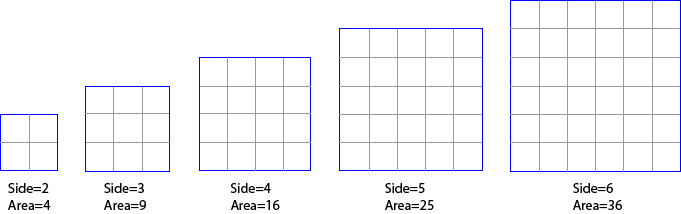
A secret to understanding decibels is to note that decibels are non linear. Another example of a non-linear relationship is between the side of a square and the area of a square.
In this example, you can see that increasing the side measurement does not have an equivalent increase in area, but a larger increase. Also, a doubling in the side length does not double the area – it is a lot more than the double! This is an example of a non-linear relationship – in this case, a small increase in the side relates to a different increase in the area. Decibels are similar. A small change in decibels relates to a different change in the ratio of the two levels being compared.
Decibels Express a Ratio
When we are talking about audio levels, we are looking at voltages, or sound wave amplitudes. (Note: power measurements (like the power differences in an amplifier) use a similar but different formula). But without getting into formulas etc, we need to accept the following summary of linear ratios of voltages and decibels. (I’m not showing the formulas or calculations because I reckon most people skip over them anyhow, and if you like formulas any search engine will give you as many as you like)
There are some interesting points highlighted by this table:
Double the voltage (x2) changes the output by 6dB (see examples below)
The easy ones to remember are x10 = 20dB, x100 = 40dB and x1000 = 60dB
For those who want to see other ratios and decibel values, you can use this simple calculator. Otherwise, just skip the calculator and read the examples below to help understand how decibels are used.
Example One: you increase the volume on a mixer or amplifier by 6dB: this is actually doubling the voltage that will appear at the output (because 6dB is a factor of 2 – see table). So, we could say the level is now +6dB. That is, relative to what the level was, it is now 6dB higher. Remember decibels are always relative to something, in this case, to what it was before we doubled (added 6dB to) the level.
Example Two: same scenario, but this time we lower the volume by 6dB. This means we are halving the voltage (because 6dB is a factor of 2). So, we could say the output is now -6dB (below what it was before).
These examples also show that it is possible to have positive and negative decibels. If the voltage is +6dB, it is twice the size as it was before. If is it -6dB, then it is half the size it was before.
I know it can be hard, but stay with me here, a few more examples should help.
Let’s say we have a microphone that is giving out 1 millivolt (that is, a thousandth of a volt) when we speak into it. We plug this microphone into a pre-amp (microphone input on a camera or mixer) that has a gain of 60dB. From the table above, we see that 60dB is equal to a linear ratio of 1000. Therefore, a pre-amp with a gain of 60dB is going to amplify our 1mV mic level signal by a factor of 1000, giving us a level of 1,000 millivolts or 1 volt. Behold, we now have a signal which is at line level (see article on Audio Levels).
Consequently, we could say that the level of the microphone signal is -60dB compared to the amplified line level. That is, the input is 1000th of what the output of the pre-amp is.
In practice, most microphones will produce about 10 millivolts (when spoken directly in to), so the signal only needs to be amplified by a factor of 100 to make it up to 1 volt (0.01 x 100 = 1.0). The table above tells us that a factor of 100 is 40dB.
Most mic pre-amps should amplify the signal by at least 40 dB (x100) and some will amplify up to 60dB (x1000). Most mixers have a gain control at the top of each channel. This will allow you to vary the gain of the preamp, to better match the input level.
Some video cameras (semi-professional or professional) will have a switch which allows you to switch the gain between 40dB, 50dB or 60dB gain for the preamp. The other way of stating this is to say the input is selected for -40dB, -50dB or -60dB levels. Just remember it is all relative, and the greater the number, the greater the amplification.
Have a look at the manual for your HiFi, mixer or video camera, and find out what level your mic input it expecting. If you are putting more in, it will probably cause distortion.
If for instance you are trying to connect a mixer (PA board) tape out, into your mic input, what do you need to consider? Well, first we need to know what the output level is likely to be. Let’s say that the specifications say the tape out (line out) is -10dBV or 316 millivolts and your mic input is looking for -50dBV (or 3.16 millivolts). This is where decibels makes it easy. We have a level of -10dB, and need to get it to -50dB, easy, use a 40dB attenuator to reduce the level. That is easier than calculating the ratio between 316mV and 3.16mV, (which when you calculate it happens to come to a linear ratio of 100 or a logarithmic ratio of 40dB).
Again, a 40 dB attenuator is indicating a ratio, in this case the ratio between the signal in and the signal out is 40dB, or a factor of 100. That is, the output is one hundredth of the input. If you want to look at other voltage gain or attenuation ratios and decibels, have a play with my Decibel Calculator for Audio
Decibels do make calculations easy, but it can be difficult to comprehend.
In the next article we look at how to read the specifications about decibels, before looking at some real world applications.
This article is based on one I originally wrote for my friends at CamcorderUser.net, and has been refined by their helpful comments
If you don’t like formulas then you definitely won’t like the formula for calculating voltage ratios expressed in decibels.
So, use the following calculators to get a handle on the decibels with different input and outlet levels.
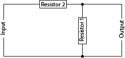
These calculators also show you the theoretical values for resistors to make your own inline audio attenuator, and a calculator to show you the actual dB attenuation with any two real world resistors.
Note: the calculator is best viewed in landscape mode on phones and small screens
Circuit for simple audio attenuator – the value of the resistors are calculated above
For a better understanding of what all this means, read the articles on Understanding Decibels Part 1 and Part 2.
For those who need to know, the basic formulas used for these calculators are :
In this article we look at S-video signal: what it is, what cables to use, where S-video is used and the problems with it. This is the second in the series of articles outlining the different video signals used in home entertainment for connecting VCRs, DVDs, set top boxes, cameras and laptops to TVs and projectors. In the previous article we looked at Composite Video.
What is S-Video?
S-Video is an improvement on Composite Video as the luma and chroma stay separated. S-Video was introduced with Super VHS Video Cassette Recorders as these higher quality devices recorded the luma and chroma separately on to the video tape. This overcame the problem of having to separate these two components in the TV, as they were already separated (they were not mixed in the first place). By keeping the luma and chroma separate throughout the whole signal path, the resulting picture appears crisper with less colour smear compared to composite video.
The “S” in S-video normally means “Super” video (like Super VHS) or “Separated” video. In a S-video signal, the sync (timing information) is still combined with the luma information. In technical articles, the luma signal (black & white picture information) is represented by the letter “Y”. Chroma (the colour information) is represented by the letter “C”. Hence S-video can also be referred to as Y/C video signal.
Cables to use for S-video
The normal connecter for S-Video uses 4 pins: 2 pins for “Y” (luma) and 2 pins for “C” (chroma). The cable needs to have two separate pairs (4 wires in total). Pre-made S-video cables are normally available in lengths up to 15 metres (50 foot). For longer cables, it is normal to use a breakout cable at each end, and install two RG59 video cables in between.
Please be careful when using a S-video plug, make sure it is orientated the right way as the pins are easily bent if forced in the the wrong way.
Click here to browse S-Video leads available from Amazon
Disclosure: If you buy through this link Geoff receives a small commission from Amazon
Some devices also use a 7 pin socket. A 4 pin S-video plug should plug into a 7 pin socket with the 4 pins connecting to the right sockets containing the luminance and chroma signal.
Where S-video is Used
S-video is not regularly used these days as there are better ways to connect video signals. However it is still widely available on many DVD players, Set Top Boxes (STB) and game consoles. Older laptop computers also have a S-video connector (although often 7 pin).
To connect a screen or projector with a S-video cable, it needs to have a S-video socket, as does the DVD player or STB.
Problems with S-video
Although S-video is better than composite video in that the chroma (colour) and luma (picture content) are separated, there are still problems with S-video. Colour content for video is made up of red, blue and green. In S-video, all this colour information is combined into one signal path and cable and is therefore compromised.
In the next articles we look at RGB video signals, and then component video, where the colour information remains separate.


 You are probably aware of the yellow, red and white connecting leads. The yellow one is generally used for composite video (the red and white ones are used for left and right sound). The plugs on each end are called RCA plugs, and these leads are normally called RCA leads, or AV leads (audio and video). These leads are good for short distances up to 5 metres (15 feet). For longer distances (to connect to a projector), thicker cable should be used for composite video signals. This larger cable is normally called RG59. It can be used for distances up to 100 metres. You can buy pre-made RG59 video cables in 5, 10, 15 and 20 metre lengths. For longer lengths, the cable is normally installed and then the connectors attached (soldered or crimped).


")

 : you increase the volume on a mixer or amplifier by 6dB: this is actually doubling the voltage that will appear at the output (because 6dB is a factor of 2 – see table). So, we could say the level is now +6dB. That is, relative to what the level was, it is now 6dB higher. Remember decibels are always relative to something, in this case, to what it was before we doubled (added 6dB to) the level.
")