In this article, we look at component video signal: what it is, where it is used, and what cables are used for component video. This is the forth in this series of articles outlining the different video signals used in home entertainment for connecting VCRs, DVDs, set top boxes, cameras and laptops to TVs and projectors. In the previous articles we looked at Composite Video, S-video and RGB video.
“Component video” could well be referred to as “confused video”. Component video is often confused with RGB video in terms of what it is. Component video can be confused with S-video as the luma (picture) and chroma (colour) components of S-video are kept as separate components. Even the phrase “component video” is easily confused with “composite video” during discussions about either. So, lets try to reduce the confusion.
What is Component video?
In the last article we saw how RGB is three coloured picture signals, and the problem is that this is a lot of information to process and store. So when DVDs were invented, they needed a way of preserving the separation of the three coloured signals, and yet reduce the overall amount of information. So instead of having the complete picture for each colour, component video uses one channel/cable to carry the basic black & white picture information (luma). As we saw in the article on S-video, the letter “Y” is used to designate the luma channel. The horizontal and vertical sync (timing information) is also combined in this channel. So the “Y” component is the basic black and white picture bit of component video. To try to confuse you, the Y (luma + sync) component is connected to the green plug and socket of connectors (even though it doesn’t carry any colour information at all – certainly no green).
So all the black & white picture information (luma) is on one channel/cable. Now what about the colour information? This is where it gets tricky. The other channels/cables in component video are called the “colour difference” signals. That is, how much blue and red there is relative to the black & white picture (luma). Mathematically, the blue component is said to be blue minis luma (B-Y), and the red component is red minus luma (R-Y).
So that is component video, just the three channels (cables) are required: Y, B-Y and R-Y. The more astute among you will want to know about the green signal. This is the clever bit: the display (TV or projector) knows how bright the image is (from the Y component). From the B-Y and R-Y components it knows how much of the image is blue and red, so it simply says the rest must be green – simple eh?
To add even more to the confusion, different terms are used to indicate each component. This table tries to make sense of it all.
Description
Symbol
Cable Colour
Label 1
Label 2
Luma + Sync
Y
Green
Y
Y
Blue – Luma
B-Y
Blue
Pb
Cb
Red – Luma
R-Y
Red
Pr
Cr
Although there are technical differences between the labels often used for component video, they are generally used to mean the same thing. So don’t be confused when you see the green, blue and red sockets labelled Y B-Y R-Y or Y Pb Pr or Y Cb Cr. These labels are mostly used interchangeably these days. As in the photo of the back of a DVD player, either type of label may be used, and sometimes both are used.
Where Component Video is Used
Component video is the highest quality analogue video signal commonly used on domestic equipment. It is used extensively on DVD players – indeed the three components of component video are separately stored on a DVD in digital form. Component video is also available from set top boxes, satellite receivers and digital recorders. It can be used for standard definition and high definition images.
Most recent TVs, screens and projectors also have the three component video connectors. Connecting the “component video out” of a device to the “component video in” of a display will give you the highest quality analogue picture available.
Cables to use for Component Video
Red, green and blue cables are most commonly used for component video. The green connector normally connects to the green socket on the sending device (DVD player or STB) and to the green socket of the display device (screen or projector). The “green” channel is normally labelled “Y”, as it is carrying the luma (black and white picture information). The red and blue plugs connect to their corresponding coloured sockets also. The cables use the same RCA (phono) plugs we discussed in the article for composite video.
There is nothing magical about the colour of the plugs and sockets. The colours are there simply to make it easy for you to connect each component of the component video from the sending device to the correct input of the display device. If you have other coloured leads, you can also use them – just make sure you connect the “Y” signal out to the “Y” signal in, and the same for the red and blue difference signals. If need be, you can even use the yellow, red and white composite video (and audio) leads for component video over short distances – just make sure the right output component video signals are connected the their respective inputs of the display device.
If the cables are not connected correctly, there is normally no damage done, but the colour of the image will be wrong. Obviously, if the “green” (Y) only is connected, you only get a black & white image. If the “red” and “blue” cables are swapped, the colours will simply be wrong (as the red and blue colour information is swapped). If the “green” is not connected correctly most displays will indicate “no signal” as it can’t detect the basic picture.
Good quality cables are required for component video, especially over longer distances. As mentioned in the article on composite video, good quality RG59 video cable can be used for lengths up to 100 metres (300 ft).
This calculator will help you determine the cable losses in distributed speaker systems (also known as 100-volt or 70-volt speaker systems). By inputting the cable size and length, and the number and details of the speakers, it will calculate the loss in SPL(dB), Voltage, and Watts. It even calculates the resultant SPL in dB at the target audience. All you have to do is fill in the white cells in the calculator.
First up, select the units of measure: either “Metres & mm²” or “Feet & AWG”. Most countries use metric, meaning the cable lengths are measured in metres, and the cable size is in mm². USA doesn’t use metric, so select “Feet & AWG” – the cable lengths will be in feet, and an extra box appears to enable you to select the cable thickness in AWG.
Then work your way down the top table:
Total number of speakers connected in the cable run.
Tap settings on speakers: Most speakers for distributed speaker systems have some way of selecting different taps, or power, for the speaker. This is normally expressed in watts.
Speaker sensitivity: this is optional, but is used to calculate the SPL level at the target audience. It is normally found in the specifications of the speakers. For example, a ceiling speaker specs might say “Sensitivity: 90dB (1w/1m)”
Distance from speaker to target audience: This is also optional and is used for calculating the SPL loss in the air from the speaker to the target audience. For a ceiling speaker it might be only 1 metre or so from the ceiling to a person standing. For a speaker outdoors, it might 10 or 20 metres or more.
Total cable length: is the total length of the cable from the amplifier to the last speaker.
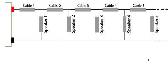
Length of feed cable to first speaker should be self-explanatory. It is the cable length from the amplifier to the first speaker. The calculator then assumes the number of speakers are evenly spread over the remaining length of the cable.
Distributed system maximum voltage is about the amplifier. Its output will be rated at 100 volts, or 70 volts, or perhaps 50 or 25 volts.
Cable c.s.a: This is the important figure as all calculations about the resistance of the cable are based on the cross sectional area (c.s.a.) of the cable. This is convenient for metric users as cables are categorised according to their c.s.a. For other users, who are used to sorting their cables according to their AWG number, the calculator inserts the c.s.a for you (based on the AWG # selected).
Once all those inputs are entered, the results are immediately calculated (actually they are calculated after every entry or change). See the remarks below if you need help in interpreting the results. For those who need to know the math behind this calculator, this is explained at the end of this article.
Note: the calculator is best viewed in landscape mode on phones and small screens
Download Calculator as Excel File
Prices in US$
What the results mean
The results of this distributed speaker system cable loss calculator basically tell you that if you don’t use too many speakers and they are not drawing much power, then you don’t have to worry too much about the cable size. However, if you have long cable runs, many speakers or high power speakers: you may need to reduce the cable length, increase the cable size, reduce the number of speakers and/or reduce the power tap on each of the speakers.
The total load of speakers and cable tells you the total load on the amplifier in ohms. Then the corresponding power from the amplifier is calculated. This figure will be less than the simple calculation of the number of speakers times the power of each speaker. This is because the cable resistance adds to the speaker impedance, which decreases the current from the amplifier, which lowers the total power output of the amplifier. The amplifier needs to cope with this total load. Good practice would dictate that you use an amplifier 20%-25% larger than the total load.
The total cable resistance is for information only.
The maximum current in the feed cable is useful to determine if the cable selected is capable of carrying that current.
The SPL difference between the first and last speaker will help determine if you need to use a larger cable or not. Many systems would cope with a difference of up to 6dB (+/-3dB). Any difference larger than 6dB would become noticeable to many users.
The results for various speakers are then tabulated. Speaker #1 is the first speaker. The results are also shown for the last speaker and the middle speaker. Although the middle speaker number can be changed to see the results of any speaker between the first and last speaker.
The Maximum SPL result is determined by the sensitivity of the speaker, the SPL loss in the air between the speaker and the target audience plus the gain of the speaker over of 1 watt.
Finally, a graph showing the calculated distributed speaker system cable losses is shown.
Assumptions of this Distributed Speaker System Cable Loss Calculator
This calculator makes several assumptions:
The calculator assumes the resistivity of copper cable is 1.724 x 10⁻⁸ Ωm. This can change slightly between single or stranded cable. Also not all copper cable is pure copper which change the resistivity slightly, as can temperature. Although in practice, these differences will have little effect on the results.
The calculator assumes the speakers are spread evenly across the cable length (after the feed cable). If the speakers are not evenly spread, there again will be little difference in the results in most cases.
The calculation for SPL loss in the air between the speaker and the target audience assumes a non-reflective space (like outdoors). For reflective walled spaces the loss could be as much as 6dB less. However the losses will still be relatively the same across the speakers.
This distributed speaker system cable loss calculator assumes the speakers are all set at the same tapping (watts) and the same size cable is used throughout the cable run. Changes to these assumptions is beyond the scope of this calculator.
Further Information
For further information about distributed speaker systems, also known as 100-volt speaker systems, or 70-volts speaker systems, read the article on Understanding Distributed Speaker Systems
Calculations used in Distributed Speaker System Cable Loss Calculator
You only need to read this if you like to know about the math or you are interested in the principles of the calculations involved. There are a number of steps involved in calculating the cable loss of any circuit.
Calculating the Resistance of the Cable
The first step involves calculating the resistance of each section of cable. The resistance in any cable is determined by the length of the cable, the thickness of the cable and the resistivity of the cable.
The cross sectional area (c.s.a) of the cable is a measurement of how thick the cable is. In the metric system cables are categorized by their c.s.a. For example: 0.75mm2 or 2.5mm2.
The c.s.a. of a non-metric cable is converted from its AWG number (gauge#) to mm2 using the following formula:
c.s.a in mm2 = 0.012668 × 92(36-gauge#)/19.5
Resistivity is the name for the inherent resistance in any material. For copper, resistivity is 1.724 x 10⁻⁸ Ωm. For practical cable loss calculations, simply multiply the resistivity by 10, then divide that by the c.s.a. (in mm2) to get the resistance per thousand meters. For example: let’s say the c.s.a of a copper cable is 2mm2:
1.724 x 10 = 17.24 divided 2 = 8.62 ohms per thousand meters.
If a cable is 100 meters long, then the resistance of the 2mm2 cable would be 8.62 ohms divided by 10 (100 meters is 1/10 of 1000 meters). That is: Resistance of 100 meters of 2mm2 cable is 8.62 divided by 10 = 0.862 ohms
It is important to note that this cable resistance is for a single copper conductor. Speaker cables have two wires, so this resistance needs to be doubled for correct calculations. Once you have the resistance of any length of cable, you can then calculate the losses of that cable.
Calculating Cable Loss
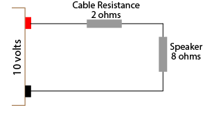
There are two way to calculate the losses of a cable. Both ways require you to know the total resistance of the circuit. Let’s look at a simple equivalent circuit to start with: an amplifier with an output voltage of 10 volts, a speaker with 8 ohms impedance, and a cable with a total resistance of 2 ohms
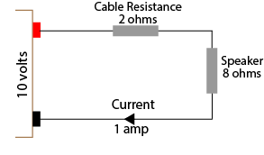
From the above diagram we can see the total load on the amplifier is 10 ohms (8+2). Ohms law allows us to calculate the current through this circuit by dividing the voltage by the resistance. That is, 10 volts divided by 10 ohms results in 1 amp flowing through the circuit.
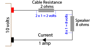
Now that the current is known you can use Ohms law to calculate the voltage loss in the cable and the resultant voltage to the speaker
To do this, simply multiple the current (1 amp) by the resistance. So the cable loss will be 1 x 2 = 2 volts, and the voltage at the speaker will 8 volts. This is the voltage listed in the table as the “Maximum Voltage at Speaker.”
Another way to easily calculate the cable voltage loss and/or speaker voltage is to simply use ratios. The voltage across the speaker can be derived by using the ratio of the speaker impedance to the total circuit resistance. For our example above, the ratio is 8:10, or 4:5 or 4/5 or 0.8 Therefore the voltage across the speaker will be 10 volts x 0.8 which equals 8 volts. This is the method used in the distributed speaker system cable loss calculator. As you can see, either method gets the same result, however the second method doesn’t require the calculation of the current through each circuit.
Calculating Maximum Power at Speaker
The maximum power at each speaker can be easily calculated since the voltage across the speaker and the speaker impedance is now known.
SpeakerPower = Voltage squared divided by impedance
Using our simple example, the voltage across the speaker is 8 volts. The impedance is 8 ohms. So the maximum power available at the speaker is 8 times 8 (64) divided by 8 = 8 watts. In the distributed speaker system cable loss calculator this is the figure stated for each speaker for “Maximum power at Speaker”.
Calculating dB Loss
The decibel (dB) loss at a speaker due to cable loss is a calculation of ratios. Either the resistance ratio or the voltage ratio can be used as both ratios are the same.
The formula for calculating decibels may look complicated, but is not too difficult with modern calculators – it just needs the “log” function. Calculators on most smartphones and computers have the log function available although you may need to invoke the scientific calculator option.
Decibel loss at the speaker = 20 times Log(ratio)
Using our simple example, the ratio of the speaker voltage to total voltage (or speaker impedance to total resistance) is 0.8. Using a calculator, log of 0.8 = -0.0969 times 20 = -1.9dB. In the distributed speaker system cable loss calculator this is the figure stated for each speaker for “SPL loss due to cable”. This is the SPL loss from the speaker compared to a circuit with no cable loss.
Calculations for Multiple Speakers
Although the above example is simple, it demonstrates the principles involved in determining the cable loss with one or more speakers. Each additional speaker requires the same calculations as above. There are two main differences. Firstly, the starting voltage for the next speaker will be the calculated voltage from the previous speaker.
The second difference is how to determine the total resistance for each speaker’s calculation. As can be seen in the above diagram, it is not easy to determine the total resistance. For this reason it is common to determine the total resistance in the circuit based on the total load of the speakers. That is, if there are 20 speakers, each 30 watts, the total load would be 600 watts. Using Ohms law, the total impedance for a 100 volt amplifier can be calculated as 16.67 ohms (voltage squared divided by power).
Alternatively, the impedance of one speaker can be calculated to be 333.33 ohms (again voltage (100 volts) squared divided by the power (30 watts)). The total impedance of 16 x 333.33 ohms speakers in parallel can be calculated as 16.67 ohms.
This figure can be used to calculate the current in the cable to the first speaker, and therefore the voltage loss in the cable and the voltage at the speaker. However the current (and voltage loss) will decrease for each speaker as the number of speakers decreases. So the current in the cable to the 2nd speaker will be determined by the impedance of the remaining 19 speakers in parallel. The 3rd cable’s current will be determined by the impedance of the remaining 18 speakers in parallel. And so on. This is the method used in the first version of the Distributed Speaker System Cable Loss Calculator.
Version 1.2 Changes
The major change in Version 1.2 of the calculator is the inclusion of the cable resistance in determining the total load on the amplifier, and in determining the total resistance for each speaker’s calculations. The first version simply used the calculated load as determined by the speaker impedance (as described above). However as can be seen in the diagram above, if the cable resistance is substantial, it will have some effect on the total resistance and therefore the total load, current and losses.
In version 1.2, the difference in the levels between speakers is normally less than 0.5dB compared to the first version. However the resistance/impedance on the amplifier is increased, therefore the amplifier power and current requirements are slightly decreased. Consequently SPL losses overall are slightly less.
What does NTSC, SECAM and PAL mean? These acronyms often pop up when setting up an analogue TV or burning a DVD video.
Basically, they are different technologies used for producing a colour picture on TV. Every country uses a version of one of these systems to broadcast colour TV. The TV must be capable of receiving the same system as is being broadcast. Modern TVs are capable of receiving most systems.
NTSC
NTSC is an acronym for National Television System Committee. It was developed in the USA and released in 1954. It is used in Japan, North America and parts of South America. A “hue” control is required to set the colour correctly. Some people therefore say the acronym means Never Twice the Same Colour.
SECAM
SECAM is an acronym for Sequential Couleur avec Mémoire or Système en Couleur àMémoire. It was developed in France and first broadcast in 1967. There are various versions of SECAM known as SECAM B or SECAM K etc. It is used in France, Eastern Europe and parts of Africa. SECAM is also known as Something Essentially Contrary to the American Method.
PAL
PAL is an acronym for Phase Alternating Line. It was developed in Germany and first broadcast there and the UK in 1967. There are various versions of PAL known as PAL G or PAL B etc. It is used in UK, Europe, Asia and Pacific Regions as well as parts of Africa and Southern America. Depending on where you live, it is also known as Perfect At Last, or Picture Always Lousy.
I like to know what technical acronyms mean as it can help in understanding the technologies involved. Let me know in the comments section below of other technical acronyms that are interesting or ones you would like to know more about.
This distributed speaker system SPL calculator takes the guess work out of which speaker tap to use. It will tell you the correct power tap for each speaker in your design. The calculator is really useful when balancing levels of different speakers. Or when the speakers are mounted at varying distances from the listener. It also helps in determining the amplifier power needed to deliver the required Sound Pressure Level (SPL) at the target audience.
For those who have played with this calculator previously, a blank version for use is just below. If you want to play with a working example of the calculator to see it in action, click here. If you need help in using the calculator, below is an explanation of all the fields and some user tips.
For further information on distributed speaker systems (often called 100-volt or 70-volt speaker systems) see my article on Understanding Distributed Speaker Systems.
Note: the calculator is best viewed in landscape mode on phones and small screens
Download Calculator as Excel File
Prices in US$
Explanation of Distribution Speaker System SPL Calculator
As with any of my calculators, you just need to fill in the white blank fields. A short explanation of each field follows.
Starting with the table at the top of the calculator:
Select the units of measure, either metres or feet. The selected unit of measure will be used for the distance from the speaker to the target audience.
Enter the required SPL at the target audience. This will depend on the ambient noise level, the purpose of the sound system (background or foreground) and how loud the system needs to be among other factors. As a guide:
65dB – 75dB for quite areas like offices
75dB – 85dB for louder areas like shops
85dB – 95dB for loud places like sporting fields
Select amplifier power output. Most SPL calculators tell you the maximum SPL possible with the amplifier running at full power. This distributed speaker system SPL calculator will do that and more, (or should I say, and less). If required, you can select full power if you want the amp to run at full power with no headroom. Simply select “Full”
You can also calculate the SPL and speaker power taps with the amplifier running at less than full power, which is often the case, and mostly preferable. As the amplifier output power is reduced, the effective power of any connected speaker is similarly reduced, as is the amplifier output voltage. For your information, the following table shows the power and voltage levels along with the effective power rating of a 30 Watt 100 volt speaker for various levels.
Amplifier Power
Amplifier Voltage
Power of 30 watt
100 Volt speaker
Full
100 volts
30 Watts
1/2 power (-3dB)
70.7 volts
15 Watts
1/4 power (-6dB)
50 volts
7.5 Watts
1/16 power (-12dB)
25 volts
1.875 Watts
Low power (1/100, -20dB)
10 volts
0.3 Watts
I suggest you try “1/16 (-12dB)” first. If the speakers can deliver the required SPL at this power setting, then the amp is not going to work hard and you have plenty of room for extra level if required. If this selected level doesn’t deliver sufficient power, try “1/4 (-6dB)”, as this level stills offers headroom.
Select the acoustic space reflectivity/reverberation. This is where any pretense of this calculator being accurate goes out the window. The calculation for SPL loss in the air is based on having no reflections to allow the sound the decay naturally. Specially designed rooms or outdoors are common examples of “dead” acoustic spaces. In such cases, select “Dead”, and no allowance will be made for reflections.
In most rooms there will be some reflections which decrease the natural losses. This calculator allows you to select if the reflectivity or reverberation of the room is judged to be Low, Mid or High.
Low (+2dB) would be for a space with lots of curtains, carpeted floor and soft furnishing. The small reflections within the room wont allow the sound to decay as well as if in the open air. So the air loss might be around 2dB less than in the open air. Or in other words, the sound level at the target audience might be increased by around 2dB.
Mid (+4dB) would be for a space with some reflections which might add around 4dB to the SPL at the target distance.
High (+6dB) would be for a space that is highly reflective with substantial reverb. Large rectangular spaces with wood or concrete floors, and acoustically reflective walls will often increase the SPL to around 6dB at the target audience.
The selection you make here is very subjective, and maybe a guess, but at least you have the ability to allow for the different acoustic spaces. If in doubt, choose “dead” for outside open areas, and “Mid(+4dB)” for indoors.
Calculate Speaker Taps
OK, you have now entered the required SPL, amplifier power setting and selected the acoustic space. Now you can now have fun with different speaker arrangements and calculate the tap setting required.
Start with “Speaker 1” and work down the table for each speaker. The calculator allows up to four speaker types to be calculated.
Speaker Description: This field is optional. It can be used to describe the speaker and anything unique to it. For example, a ceiling speaker might be mounted at a height of 3.2 metres. A while a similar speaker might be mounted on ceiling that is 5.2 metres high. There might also be a box type speaker mounted 5.2 metres high. Entering these descriptions for each speaker install is useful to avoid confusion. If entered, these descriptions are also used in the graph at the bottom of the calculator.
Speaker Sensitivity: This figure is normally found in the specifications for the speakers. For example, a ceiling speaker specs might say “Sensitivity: 90dB (1w/1m)”. For an explanation of speaker sensitivity and how we use it to determine the SPL of a speaker, see my article “Understanding Speaker Sensitivity“
Distance to Target: This is the distance from the speaker to the listener. For ceiling speakers it would be the height of the ceiling minus the sitting or standing height of the listener.
Once these figures are entered, the following are calculated for each speaker:
SPL loss due to Distance: This is the SPL loss through air. This figure is dependent on the distance between the speaker and the listener, and the acoustics of the room/space (that you entered at the top of the calculator).
Required Speaker gain over 1 watt: We hardly need a spreadsheet to calculate this. It is the SPL of the speaker at 1 watt, minus the air losses, compared to the required SPL. In the example calculator below, speaker 3 will produce 84dB with 1 watt going into it, when you measure the SPL 1 metre away. So 84 minus the air loss (8dB) leaves us 76db. This is 6dB below the required 82dB, so the required gain from the speaker is 6dB. This is how much power over 1 watt we need from the amplifier for the speaker output to reach the required SPL.
Speaker power required: This calculation converts the required dB gain over one watt into watts. It also takes onto account any “de-rating” of the speaker power due to it not being driven to full capacity (see table above). This figure is the theoretical value the speaker tap should be set at to attain the required SPL at the target distance.
However, most speakers will not have a tap at that precise level. So, on the next line you need to input the value of the closest tap to the theoretical level.
Actual power tap setting: In the example below, the theoretical speaker power required for the ceiling speakers is 1 watt and 4 watts. However let’s say our ceiling speakers have taps at 10, 5, 2.5 and 1.25 watts. For speaker 1, we could use 1.25 watts instead of the theoretical 1 watt. For speaker 2 we could use 5 watts, instead of the theoretical 4 watts. Speaker 3, the box speaker might have taps at 30, 15, 7.5 and 3.75 watts. Choosing 15 watts instead of the theoretical value of 16 watts, results is only 0.3dB difference in SPL at the target audience distance.
Calculated SPL at target: is the SPL at the target audience distance with the actual speaker power tap. These results are displayed in the graph at the bottom of the calculator.
Difference to required SPL: is the difference between the calculated SPL for the speaker tap, and the required SPL. This number will be positive if the speaker output is above the required SPL. It will be negative if it is below the required SPL. If the difference is only 1-2 dB, it will be barely noticeable. If the difference is over 6dB, then a different speaker or different tap should be used.
The graph reflects any change to any of the values in the tables. It is interesting to change the amplifier power to “Full”, you will see the SPL level raises, as you would expect. However, the dB difference between any of the speakers to each other is the same.
Once you know what taps you will be using for each speaker type, you can multiply the number of similar speakers by the actual tap value to determine what size amplifier you should use. Keep in mind, that good practice suggests to use an amplifier 20-25% greater than the total load.
How much do you need to increase the gain of an amplifier to make it sound twice as loud: 3dB, 6db or 10 dB?
This amplifier power and volume calculator will help you understand that doubling the amplifier power does not double the sound pressure level (SPL) or the perceived loudness.
You can also use this amplifier power and volume calculator to see what effect a bigger amplifier may or may not have on the perceived volume.
Note: the calculator is best viewed in landscape mode on phones and small screens
Most countries have a stated maximum continuous noise level over a continuous 8 hour period (a working day). This is normally agreed to being a maximum continuous noise level of 85dB for 8 hours.
Some authorities then say for every 3dB increase of continuous noise level, the maximum exposure time is halved.
Other authorities say for every 5dB increase of continuous noise level, the maximum exposure time is halved.
These calculators show results for both the 3dB standard and the 5dB standard. Check your local authority to know which standard you should use.
There are two calculators, the first converts the hours of continuous exposure under 8 hours to maximum continuous noise levels (in decibels) over that exposure duration.
The second calculator converts the continuous noise level over 85dB to the maximum continuous exposure time for that noise level.
Note: the calculator is best viewed in landscape mode on phones and small screens
For those who need to know, the formulas used for the 3dB standard calculations are:
Energy efficient LED lamps for lighting are very popular. They certainly cost less to run than conventional lamps. But how much do you really save, and how long does it take to pay off the purchase price of the lamps?
This calculator shows how much your existing lamps cost to run, how much you can save each year with energy saving lamps, how long it will take to pay off the purchase price from the saving you make as well as showing the approximate reduction of CO2 emissions .
You need to input 7 figures:
1. Cost of one kilowatt hour (kWh) of electricity. This should be on your power bill.
Eg: your electricity costs 25 cents/kWh – enter 0.25 in the calculator
While the results are shown in $’s, they will be correct for whatever currency you use here.
2. How many hours the lamps are on each day. This is an estimate of the average hours used.
3. Number of lamps you are thinking of upgrading, or the number of lamps in one room.
4. Wattage of the existing lamps. Halogen down lights are typically 50 watts each. Most lamps have their wattage written on them.
5. Wattage of the proposed new lamps. Energy efficient lamps may only draw 4 watts, 7 watts or some other low value. Enter the wattage value of the lamps you propose to use.
6. Cost of new lamps. Enter the cost for one of the new lamps. The calculator will multiply this cost by the number of lamps entered earlier.
7. Total cost of installation labor. Enter the estimated cost for an electrician to change over all the lights. If you are doing this yourself, or a friend is doing it for free, enter 0.
Optional: Generator Type. This is used to determine the CO2 emissions. Select the type of electricity generator your supplier mostly uses. If you don’t know, don’t worry, the energy savings will still be calculated, but the emissions savings may not be correct.
Note: the calculator is best viewed in landscape mode on phones and small screens
For those who need to know, the calculations are based on the following formulas:
Savings = existing costs – proposed costs
The carbon dioxide emissions calculator is based on:
Generator
Technology
Estimated
CO2(g)/kWh
Coal
820
Natural Gas
490
Solar PV (rooftop)
41
Hydro Electric
24
Nuclear
12
Wind
11
These values are taken from the 2014 Intergovernmental Panel on Climate Change Life Cycle CO2 Equivalent from selected electricity supply technologies as listed on Wikipedia.
Knowing the cost of running an electrical appliance is useful, and easy with this power usage calculator.
You need to know three things:
1. Cost of one kilowatt hour (kWh) of electricity. This should be on your power bill.
Example: your electricity costs 24.5 cents/kWh – enter $0.245 in the calculator
You can still use this calculator even if your currency is not dollars – just enter the cost per kWh in your currency and ignore the $ sign.
2. The power used by the appliance. The power rating of an appliance is normally written on a sticker, label or plate (often at the back or under the appliance). It is also common these days for manufacturers to state the standby power of their appliances, although you may need to find the detailed specifications to read this.
The stated power of a light bulb might be 60 watts, or an electric heater might be 1000 watts.
You can also use a simple power meter.
Click here to browse simple power meters available from Amazon
Disclosure: If you buy through this link Geoff receives a small commission from Amazon
3. How many hours the appliance is used in a day. This is an estimate of the average hours used. To calculate standby power, enter 24.
Note: Some appliances like heaters, fridges and air conditioners do not use their rated power all the time they are on. These appliances normally have a thermostat allowing them to turn off when the desired temperature is reached. Therefore the hours of use entered in the calculator can be less than the actual hours of being on.
Here is a simple calculator for power, current, voltage and resistance (actually there are 6 different calculators, use the one relevant to the values you know and the values you need to know.
Note: the calculator is best viewed in landscape mode on phones and small screens
Here is a quick reference with all the possible formula combinations. You may like to print it out and stick it to your multi-meter case or workshop wall for handy future reference.


 used to mean the same thing. So don’t be confused when you see the green, blue and red sockets labelled Y B-Y R-Y or Y Pb Pr or Y Cb Cr. These labels are mostly used interchangeably these days. As in the photo of the back of a DVD player, either type of label may be used, and sometimes both are used.
 The green connector normally connects to the green socket on the sending device (DVD player or STB) and to the green socket of the display device (screen or projector). The “green” channel is normally labelled “Y”, as it is carrying the luma (black and white picture information). The red and blue plugs connect to their corresponding coloured sockets also. The cables use the same RCA (phono) plugs we discussed in the article for composite video.


 and Time Exposure Calculator")