Distributed speaker systems are also known as “100 volt line” or “70 volt line” speaker systems. They are used extensively where multiple speakers are required. Distributed speaker systems are commonly used in airports, shopping centers, schools, churches, clubs, offices, car-parks, sports grounds and anywhere multiple speakers are required. They can also be used in homes for background music systems.
Advantages of Distributed Speaker Systems
The main advantages of distributed speaker systems are:
- No need for complicated calculations of total speaker impedance – simply add together each speaker’s wattage (see below for more details)
- Many speakers can be connected to an amplifier.
- Extra speakers can normally be added to the system
- The volume of each speaker can be adjusted independent of the main volume (so the toilet speakers are not as loud as the foyer speakers).
- Smaller cables can be used. Distributed speaker systems use much less current through the speaker cables
- Longer speaker cables are possible with minimal line loss. Cables runs can be 100’s of metres or 1000’s of feet.
Disadvantages of Distributed Speaker Systems
The main disadvantages of distributed speaker systems are:
- Each speaker requires a step-down transformer
- The transformers affect the quality of the sound – typically the lower frequencies are not transferred as well as a speaker system without transformers.
- Without using expensive transformers, use is often limited to paging, voice and low level (background) music installations.
Distributed Speaker Systems Overview
The basis of distributed speaker systems is similar to the way electricity is distributed. Power stations use step up transformers to distribute power as high voltage, which means low current, and therefore low line losses and thinner cables. Each town and/or street then converts this high voltage/low current down to low voltage/high current (through step down transformers) for use in your home.
Distributed speaker systems use a similar principle. The amplifier normally has a step-up transformer built into it, producing a high voltage/low current output. Then each speaker has its own step down transformer to convert the signal back to low voltage/high current. This allows the cable to be very long without having any significant line losses.

100 Volt Line Speaker System
The most common “high” voltage used in distributed speaker systems is 100 Volts. In many countries distributed speaker systems are known as “100 Volt line” speaker system. In a 100 Volt line speaker system the output of the amplifier is marked “100 volt”. Indeed at full output, the amplifier puts out 100 volts RMS. Each speaker then has a transformer to reduce the 100 volt line level down to normal speaker level.
70 Volt Line Speaker System
In North America the most common “high” voltage for distributed speaker systems is 70 Volts. This is because years ago, some states had laws stating that any cable with a maximum voltage greater than 100 Volts peak had to be installed in conduit. This was time consuming and costly to install. So they developed a system where the output voltage of the amplifier was a maximum of 100 Volts peak. This equates to 70.71 Volts RMS. This is commonly known as a “70 Volt line” speaker system. The principle is the same as for 100 volt line systems, but uses a maximum output voltage of 70 Volts. While 70 volt line systems are still the most common in the USA, some 100 volt lines systems are being used.
50 Volt Line and 25 Volt Line Speaker Systems
Less common, but still seen on some amplifiers and speakers are 50 volt line or 25 volt line settings. The principles are the same for all voltages, but the lower the voltage, the more current, therefore the shorter the maximum cable length without significant line losses.
In practice, many commercial amplifiers and speakers have multiple taps. They may have 100 and 70 Volts, or 70 and 25 Volts, as well as 4 ohm and 8 ohm outputs for normal speakers (without transformers). Normally you should only use one output of a amplifier, that is, either the 100 volt line output, or the 70 volt line output or the 8 ohm output, not all at the same time.
Transformers
Every speaker in distributed speaker systems needs to be connected to a step down transformer. This converts the high voltage level down to normal speaker level.
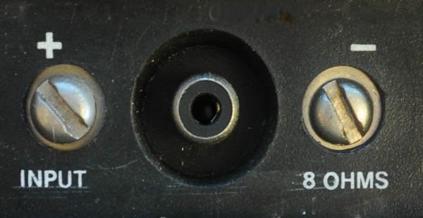
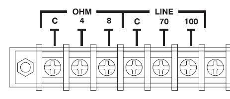
One side of the transformer normally has a common (or “0 volts”) and a 4 ohm and 8 ohms connection. An 8 ohm speaker would be connected to the common and 8 ohm taps, while a 4 ohm speaker would be connected to the common and 4 ohm tap.
Most transformers have a selection of input taps. The example in this picture has taps for 20 Watts, 15 Watts, 10 Watts and 5 Watts. The feed cable is connected to the common and any one of the other taps. This allows the relative volume of the speaker to be set during the installation. For example the speaker in a high noise room might be set on 20 Watts, while the speaker in a small, low noise area might be set on 5 watts. Alternatively, the distance between the speaker and the target audience might be different, so the speakers further away can be set at a higher power tapping (or the close speakers at a lower power tapping). To help in determining the correct tap for each speaker in every situation, see my SPL calculator for distributed speaker systems.
All amplifiers designed for use with distributed speakers systems have a step-up transformer built-in. It is also possible to add an external transformer to an amplifier without an integrated transformer. Simply use a speaker transformer in reverse – that is, connect the common and 8 ohm transformer connection to the common and 8 ohm speaker output of the amplifier. Just make sure the amplifier and transformer are rated with enough power to drive all the speakers to be connected (see Connecting Multiple Speakers below).
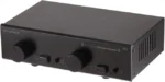
Amplifiers
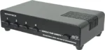
As stated above, most amplifiers designed for distributed speakers systems have the output transformer built-in. They may have various outputs for 100 volts, 70 volt and/or 4 or 8 ohms (for normal speakers).
Most 70 volt amplifiers or 100 volt amplifiers also have an input mixer built-in. This allows convenient connection of microphones and line level inputs. Ensure the model you use has sufficient inputs for your current needs, and perhaps some spare inputs for the future.
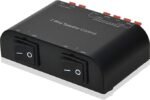
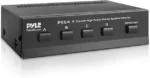
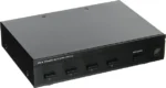
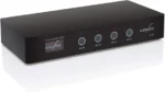
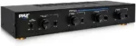
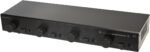
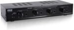
For multi-zone systems, you can purchase an amplifier with 2 or 4 amplifiers and transformers built in the one box.
Click here to browse
70V/100V amplifiers available from
AmazonDisclosure: If you buy through this link Geoff receives a small commission from Amazon
Speakers
Any speaker can be used in a distributed speaker system, as long as a step-down transformer is used. Many manufacturers produce speakers with integrated transformers for use in distributed speaker systems.
Ceiling Speakers
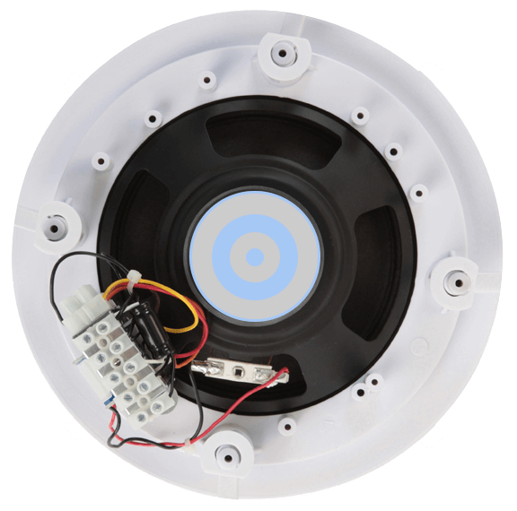
Ceiling speakers are used in many distributed speaker system installations to cover large areas and/or multiple small rooms or areas. The speaker cable is normally connected directly to the transformer. To change the power settings you need to connect the speaker cable to a different transformer tap. In the speaker pictured, this is a simple matter of moving the speaker wire to a different terminal connector.
Click here to browse
70V/100V ceiling speakers available from
AmazonDisclosure: If you buy through this link Geoff receives a small commission from Amazon
Wall Mount Speakers
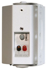
Wall mount 70V100V speakers come in all sorts of shapes and sizes. Many manufactures make a version of their cabinets with an integrated transformer. Connections are often by some form of speaker terminals. To change taps, simply rotate the switch to the desired power setting. Often these switches also have a position for 8 ohms (bypassing the transformer) – this makes them very versatile speakers for the installer. Wall mount speakers (which can also be mounted from a ceiling) are used where ceiling speakers aren’t practical, or where higher sound levels are required.
Click here to browse
70V/100V wall mount speakers available from
AmazonDisclosure: If you buy through this link Geoff receives a small commission from Amazon
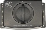
Horn Speakers
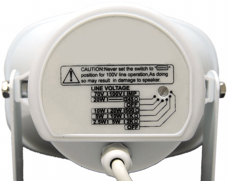
Horn speakers are very efficient, but not very good quality. They are mostly used outdoors when coverage of a large, or high noise, area is required. For example in car parks, sports grounds, school yards and other outdoor areas. In the picture shown, the rear of the horn has a selector switch which needs a flat bladed screw-driver to operate. This is useful to reduce the likelihood of inadvertent changing of the settings after the install.
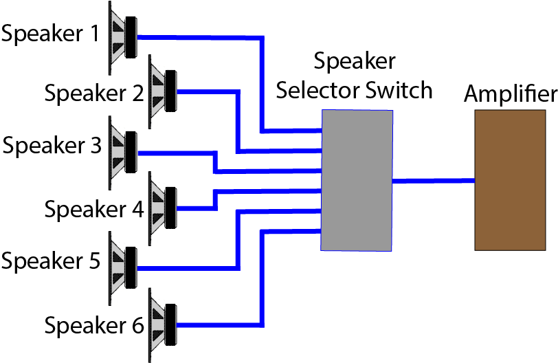
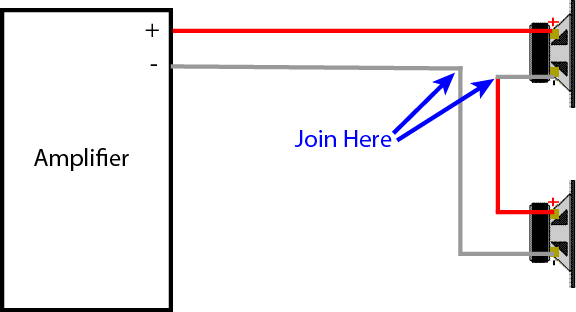
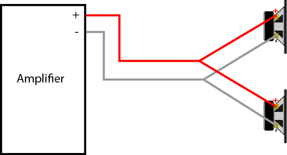
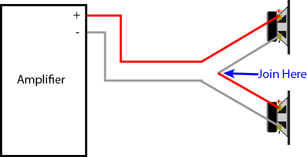
Connecting Multiple Speakers
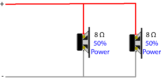
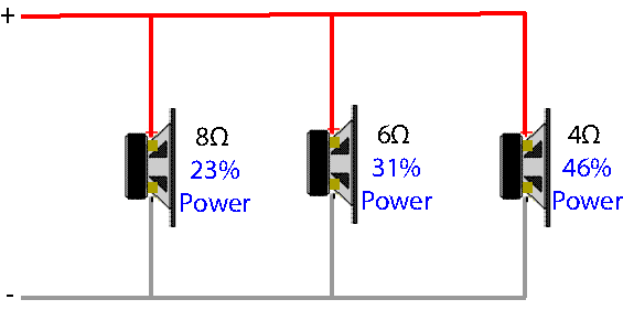
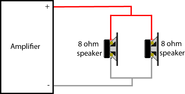
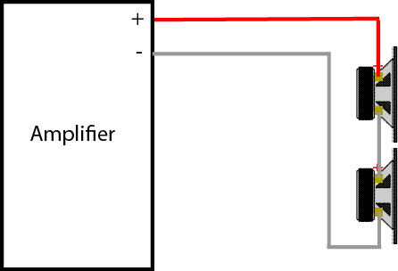
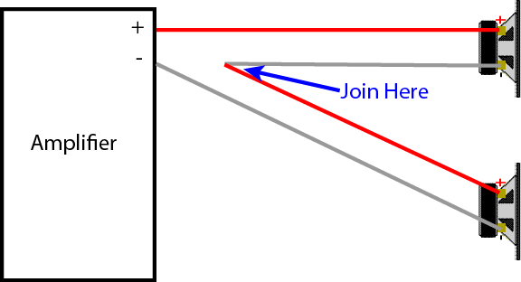
This is the fun bit, because there is no need to calculate the total impedance. To connect multiple speakers in distributed speaker systems, just wire them all in parallel and add up the total watts.
Example 1: A PA amplifier is rated at 120 watts @100 volt line. Therefore you could connect:
- 20 x 5 Watt (100 volt) ceiling speakers (total 100 Watts), or
- 40 x 2.5 Watt (100 volt) ceiling speakers (total 100 Watts), or
- 10 x 5 Watt (100 volts) ceiling speakers and 20 x 2.5 Watts (100 volt) ceiling speakers (total 100 Watts), or
- any combination of speakers that add up to no more than 120 Watts.
Example 2: A small church has a small 25 Watt (70 Volt) PA amplifier with 4 small speakers mounted in the church (2 down each side). They now want to add a speaker in a separate room for an overflow and creche area.
- 4 existing speakers can be wired at 2.5 Watts (70 Volt), total of 10 Watts
- A new box speaker can be wired at 10 Watts (70 Volt), this allows it to be louder than any of the small church speakers (since the creche area has much more ambient noise levels).
As shown, it is easy to add the individual speaker watts together. This is much easier than calculating the total impedance.This makes installation much simpler.
Calculating Watts from Speaker Impedances
Sometimes manufacturers of speakers designed for distributed systems only mark their speakers with the impedance of each tap, rather than the Watts. Also, many impedance meters tell you the impedance, and you need to calculator the wattage.
In either case, you can use this simple calculator:
Tips for Using Distributed Speaker Systems
Following are some practical tips for installing distributed speaker systems:
- Keep all the speakers in phase. This means the the “O volt” or the “Com” of the amplifier speaker terminal should be connected to the “O Volt” or “Com” of each speaker transformer.
- It is good practice to design distributed speaker systems to use up to only 80% of the amplifier’s total available power. For example, a 120 Watt PA amplifier should only be connected to a maximum of around 100 Watts of speakers. This helps avoid the amplifier’s transformer distorting from saturation (overload), allows for inefficiencies in the system, and allows an extra speaker to be added if required in the future.
- When designing distributed speaker systems, calculate the total watts of the speakers, and select an amplifier larger than required. For example, If an install requires 10 speakers at 5 Watts each (total load of 50 Watts), a 60 Watt amplifier could be used, but selecting a 100 Watt or 120 Watt amplifier will allow speaker taps to be changed or extra speakers added in the future. It is a relative small increase in price to up-size the amplifier before purchase, rather than have to buy a new one later.
- When selecting speakers, chose a higher power one than required. For example: If a 5 Watt ceiling speaker is required, chose a 10 Watt or 15 Watt speaker and use the 5 Watt tap on the transformer. This again reduces the likelihood of overloading cheaper transformers, and gives the ability to increase the power level (volume) if required.
- When connecting many speakers, it is good to have multiple feed cables. For example; if connecting 60 speakers, it is possible to use one speaker cable run and loop in and out of each speaker. However it is better to have several feed cables to smaller groups of speakers. This way if a fault occurs, it is easier to isolate which feed the fault in on. Also the total load (and cable loss) is shared by each cable run. If you have long cable runs, see my Cable Loss Calculator to ensure you use the right size cable.
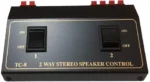
- It is possible to get some speakers with a built-in attenuator to control the volume of the speaker. This is useful in situations when you want the listener to control the volume. For example in a creche. It is also possible to get external attenuators to control the volume in a room or for an individual speaker.
- If possible, measure the impedance of each speaker feed cable before connecting the amplifier. This is best done with an impedance meter. If installing a number of distributed speaker systems, an impedance meter is very useful.
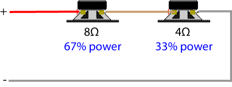
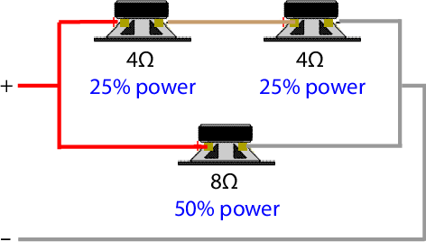
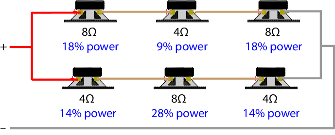
- Don’t connect a 4 ohm or 8 ohm speaker directly to a 100 volt line or 70 volt line speaker cable. Apart from severely overloading the speaker (and possibly burning it out) a 4-8 ohm speaker effectively puts a short circuit on the speaker line and overloads the amplifier. See the calculations below for the mathematical explanation of this.
- If a 100 Volt line amplifier is overloaded, connecting the load to the 70 Volt line effectively halves the load on the amplifier and it will not be overloaded. However the maximum power to each speaker (and therefore the speaker output) is reduced by 3dB.
- Example 1: The total watts of all the (100 Volt) speakers totals 200 Watts. If connected to the 100 Volt line speaker terminals of a 120 watt (100 Volt) amplifier, the amplifier will be overloaded. Connect the same speakers to the 70 Volt line terminals of the same 120 watt amplifier and the amplifier will only see a load of 100 Watts.
- Example 2: The total watts of all the (70 Volt) speakers totals 50 Watts. If connected to the 70 Volt line speaker terminals of a 40 watt (70 Volt) amplifier, the amplifier will be overloaded. Connect the same speakers to the 50 Volt line terminals of the same 40 Watt amplifier and the amplifier will only see a load of 25 Watts.
- You can use the calculator above to see this by selecting the different system voltages. For those whose like to know, the mathematical explanation of this is below.
Summary
Distributed speaker systems are ideal for multiple speaker installations. They allow long speaker cables and calculation of the total load is easy. Distributed speaker systems are normally mono (not stereo). They are mostly used for paging and background music situations. Although normally used for commercial installations, they can be used in domestic installations for background music systems
Below are some of the major calculations used with distributed speaker systems (you can stop reading now if you are not into calculations).
Calculations for Distributed Speaker Systems
The following calculations are for those who like to understand the mathematics behind the principles outlined above. You don’t need to understand these calculations to use distributed speaker systems, but it will help you understand and design systems better.
Several principles of distributed speaker systems have been outlined above. A mathematical explanation of each principle is now given under the following sub-headings:
Adding the Power of Each Speaker
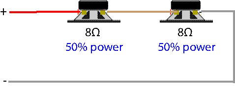
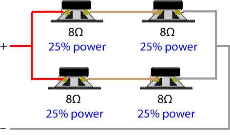
As an example, four 5 Watt speakers are connected together (in parallel) to a 100 Volt line amplifier.
The simple way to calculate the total load is to add 5 + 5 + 5 + 5 = 20 Watts.
The harder way (which is why its not normally done) is to calculate the impedance of one speaker, and then calculate the total impedance of 4 such speakers in parallel, and then calculate the total power.
So the impedance of a 5 Watt speaker on a 100 volt line:

That’s right, the impedance of a 5 Watt speaker with a 100 volt transformer is 2,000 ohms. Now to calculate the total impedance of four of these connected in parallel:
 so
so 
therefore R (total) = 500 ohms.
Now the total power of 100 Volts with a total impedance of 500 ohms can be calculated:

Low and behold, that is the same as simply adding the speaker watts together – which is much simpler!
Changing the Amplifier Connection Halves the Load
Example 1: The total impedance of 200 watts of 100 Volt speakers can be calculated:

Now look what happens when that same 50 ohm speaker load is connected to the 70 Volt terminal of the amplifier:
 .
.
Amazing, the same 50 ohm load draws 200 watts of power on a 100 volt line system, but only 100 watts on a 70 volt line system.
Example 2: The total impedance of 50 watts of 70 Volt speakers can be calculated (remember 70 Volt line is actually 70.71 Volts):

Now look what happens when that same 100 ohm speaker load is connected to the 50 Volt terminal of the amplifier:

This principle is very handy to the installer if the power required by the speaker load is greater than what the amplifier can deliver. Simply move to the lower line voltage speaker connection (on the amplifier) and the power drawn is halved. The maximum power to each speaker is also halved, so the speaker output is halved, or reduced by 3dB, but the amplifier will not be overloaded.
A 8 Ohm Speaker will Overload a Distributed Speaker System
In the examples above we saw the speaker impedance of distributed speaker systems is reasonably high. For example a 5 watt speaker on a 100 Volt line has an impedance of 2,000 ohms. Even a 125 Watt load of 100 Volt speakers is 80 ohms. So imagine the load if the total impedance is only 8 ohms. It should be 10 times the load right? This scenario can be calculated:

That’s right, connecting a low impedance speaker (4 or 8 ohms) to distributed speaker systems will drastically increase the load on the amplifier.


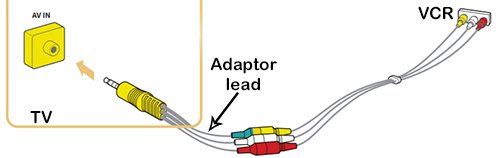


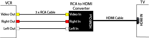
 and the reverse, a HDMI to RCA converter. To connect a VCR to a TV using HDMI, you need a RCA to HDMI converter.


 so
so 


 .
.


")