Home Blog Page 4

Reflections on the TV Remote Control

The recent passing of Eugene Polley, the man known for inventing the remote control, has given me cause to reflect on the development of the remote control. In just my life time, the humble TV remote control has come into existence and been developed rapidly.

Introducing the Flash-Matic Remote Control

Eugene Polley worked for American firm Zenith Radio Corporation (now owned by LG). In 1955 he invented the Flash-Matic, a light beam which was aimed at one of four different light sensors around the TV screen. It was possible to turn the TV on and off, and change channels. The 1956 ad for this ground breaking invention is reproduced below.  I like the line about it being “Absolutely harmless to humans!” It has been reported that this early system did have some problems in bright lights. However it is the forefather of the modern remote control which we now take for granted.

Introducing the Computermatic Remote Control

Early B&W and Colour TVs used a large channel knob to change channels. This required actually getting out of your chair to change channels (and to adjust the volume too). Therefore it was exciting to visit my grandparents house as they had a “computermatic” TV. This 1962 TV used a motor to rotate the channel changer. It also used a wired remote control, similar to the picture. Although there was a lead between the TV and the operator, it did allow remote control of the sound, picture (brightness) and the ability to change channels from the lounge chair. The channel button on the TV and the remote were labelled “FWD” and “REV”, as the motor rotated in the forward or reverse direction to change channels. This remote control also had a feature modern remote controls don’t have. Built into the remote control was a small speaker. The slide switch at the bottom of the remote control allowed the sound to come from the TV (receiver), the remote speaker, or to mute the sound. This allowed a young Geoff to watch and listen to TV when everyone else was in bed  – without disturbing them. The other good thing about this wired remote control is that it was hard to loose down the side of the lounge – you simply followed the lead to find it. It also did not require batteries!

 Wired Remote Controls

Wired remote controls became popular with many early Video Cassette Recorders (VCRs) . These wired remote controls allowed some tape playback control, mainly play/pause along with fast forward and review.

I recall around this era making a remote volume control and adapting our family TV to enable this volume control to adjust the TV sound – via a wire of course. But hey, this was a huge leap in interactive technology at our home, and the envy of many friends – fancy not having to get up to adjust the volume of the TV!

A good thing about these wired remote controls is that they were duplicating the controls on the front panel of the VCR, not replacing them. All functions could be easily controlled from the VCR even if the remote control was not lost or not working.

Cordless Remote Controls

The cheap availability of electronic tuners in TVs (and VCRs) made easy (and cheap) remote channel selection possible. This spawned the era of the common cordless remote control. So common, it seems every piece of home entertainment equipment needs its own remote control.

Apart from making you lazy by not having to get up to adjust the TV, these remote controls have raised several other issues. Not the least being many devices now rely on the remote control. If the remote control stops working or is lost, it is almost impossible to use most functions on the device.

Another issue is the problem of having to have a different remote control for each device. While universal remote controls are available, they don’t suit everyone, and can be more complicated to use, and they don’t always allow every function of the original remote control.

Taming the Remote Controls

A simple method to help manage several remote controls is to mount them on a board (a custom made board or a chopping board works well). Having all your remote controls mounted on the one board has several advantages:

  • as the remote controls are always in the same order it is easy to know which one to use for each device.
  • because they are in the same position, you quickly learn which button to press for each function.
  • they are always facing the same direction so you don’t need to turn each remote around to point it in the correct direction
  • a board is harder to loose down the side of the lounge

The Best New Feature

In my opinion the best new feature since the introduction of remote controls is shown in this picture. It is the little plastic tether strap which connects the battery cover to body of the remote control. This prevents the battery cover from being lost misplaced. Why wasn’t this thought of years ago?

Please leave your thoughts on the pros and cons of remote controls in the comment section below.


Understanding Audio Frequency

Every sound we hear is at a certain frequency. When we say someone has a deep voice, we are describing a voice producing low frequencies. Similarly if we say someone has a high pitched voice, we are describing a voice producing higher frequencies. So, what is frequency?

What is Frequency?

Technically, frequency is the number of waveforms generated in one second. As an example, if you hit the middle C key on a piano, the strings in the piano will vibrate back and forward around 261 times per second. This produces a sound wave which repeats itself 261 times each second. Therefore the frequency of middle C is 261 cycles (of the sound wave) per second.

Hertz is used as the unit of measurement for frequency in honour of the German physicist Heinrich Hertz for his work on radio waves

Rather than using “sound waves per second” or “cycles per second”, the word Hertz was adopted as the international SI unit for frequency in 1930. Hz is used as the shortened form of hertz. One hertz is the same as one wave form or one cycle per second.

Being a metric unit, the prefix kilo (k) is used for larger numbers. Example 1: A frequency of 1000Hz can also be called 1kHz, often simply called 1k. Example 2: 10k is short for 10kHz or 10,000Hz.

Music and Frequency

We saw earlier that the musical note middle C has a frequency of  261Hz (261.626Hz to be more precise). On a 88 key piano the lowest A note is 27.5Hz. The highest A note is 3520Hz. The following table gives the frequency of each A note for each octave on the piano, starting with the lowest.

A0A1A2A3A4A5A6A7
27.5HZ55Hz110Hz220Hz440Hz880Hz1760Hz3520Hz

There are a couple of interesting points to see from this table. Firstly, the frequency of any note doubles as you go up one octave. Consequently, the frequency of any note halves when you go down one octave. Secondly, most of the notes of a piano have a frequency below 1000Hz.

It is also interesting to note that the piano has a very wide range of frequencies compared to most other instruments. See the table below for a few examples (frequencies rounded to the nearest whole hertz).

InstrumentLowest FrequencyHighest Frequency
Double Bass41Hz247Hz
Cello65Hz988Hz
Guitar82Hz880Hz
Clarinet165Hz1567Hz
Violin196Hz3136Hz
Flute262Hz3,349Hz

The human voice also has a limited frequency range. The following table gives the approximate range of frequencies for different types of singers.

Singer TypeLowest FrequencyHighest Frequency
Bass82Hz330Hz
Baritone87Hz350Hz
Tenor130Hz525Hz
Contralto175Hz700Hz
Soprano260Hz1,050Hz

Harmonics

While all the above is interesting, instruments and voices don’t just produce one fundamental frequency for each note as listed above. They also produce what is known as harmonics. Harmonics are multiples of the fundamental frequency. For example, if you produced a sound at 1000Hz, there would also be sounds at 2000Hz, 3000Hz, 4000Hz and so on at various levels. The following table may help:

NameFrequencyFormula
Fundamental Frequency1000HzFundamental Frequency x 1
1st Harmonic2000HzFundamental Frequency x 2
2nd Harmonic3000HzFundamental Frequency x 3
3rd Harmonic4000HzFundamental Frequency x 4
etcetcetc

The point being, any microphone, amplifier and speaker system needs to be able to reproduce more than just the basic fundamental frequencies. Also the harmonic frequencies need to be considered when adjusting the tone of any instrument or voice. More on this in a later article.

Our Frequency Range

It is generally accepted that the hearing range of humans is 20Hz to 20,000Hz (20kHz). While we lose the ability to hear higher frequencies as we age, 20Hz to 20kHz is generally considered to be the human hearing range. It would also be good if the frequency range of any sound system was also 20Hz to 20kHz. However, very few sound systems are capable of this full range – especially at the bottom end (the lower frequencies). Nor do all sound systems necessarily need to be capable of 20 to 20kHz – it all depends on the intended use (and budget).

It is useful to know how to read a frequency chart which shows the frequency response of a speaker or microphone. The following is an example of a frequency chart for a speaker.

The first thing to notice is the scale at the bottom. On this chart it starts at 50Hz and displays numbers for 100Hz, 500Hz, 1kHz, 5kHz, 10kHz, 20kHz and 40kHz. Notice how it is not linear, but rather it is spread out over the lower frequencies and bunched up more over the higher frequencies. This logarithmic scale also closely matches the spread of frequencies we saw when looking at the piano frequency range.

The blue line is indicating the frequency response of the speaker under test. This speaker has a fairly flat response across the entire audible frequency range, with a drop off at the bottom end around 70Hz.  You may see graphs like this for speakers and microphones. They are useful to alert us to any major troughs or peaks in the frequency response which will need to be dealt with for good sound – mind you, if there are major peaks or troughs, you will probably hear that it doesn’t sound right.

This introduction on audio frequency gives a basic understanding of the principles involved. This topic will be expanded when looking at equalization and system setup.

How do I connect a PVR to a flat screen TV

PVR is an acronym for Personal Video Recorder. A PVR is the new video cassette recorder (VCR). It works similarly to a VCR, but instead of using video cassette tapes, it simply records to a Hard Disk, similar to what is in a computer.  Since modern TV signals are digital, it makes sense to record the digital data on a digital data storage device, like a hard disk. It allows the digital signal to be recorded and played back in much better quality than using an older VCR.

Which Connections

connections rear
Common connections seen on the rear of a PVR

There are a number of different connecters on the rear of a PVR. These are summarised in our hierarchy table of video signals and cables (click here for details). But before we look at the video and audio connections, let’s deal with the antenna/cable connections.

Antenna In – Antenna out

There is normally a cable coming from a connection on the wall (wall plate)  to the antenna/cable “in” socket of the flat screen TV. This is where the TV signal is connected. The signal comes from an antenna on the roof or from the cable company to the wall plate.

What you need to do is to loop this cable via your PVR. This will require a 2nd antenna cable to be used – this is often supplied with your PVR.

The antenna out socket of the PVR may be marked “Loop Out” or “Antenna Out” or” To TV” or something similar. By looping the input signal via the PVR the signal is available to both the flat screen TV and the PVR. This way, you are able to watch your programs on the TV and/or via the PVR and/or record one program and watch another, as the incoming signal is now available at both the PVR and the flat screen TV.

So, this has the input signal sorted, now we need a way of getting the recorded video and audio from the PVR to the TV. We will follow the order of quality as listed in the hierarchy table of video signals and cables.

HDMI

The best and simplest way of connecting a PVR to a flat screen TV is by using a HDMI lead. This connects the digital video and audio from the PVR to the flat screen TV all in the one cable.

In the above example, the PVR is connected to HDMI input 1 of the flat screen TV. So to watch the PVR, simply select the HDMI 1 input on the flat screen TV. This is normally done on the TV remote control by pressing the “input” or “source” button.

Component Video and Audio

If your PVR or TV does not have a spare HDMI socket, then you can use the component video cables (three in total) and left and right audio cable for the connection.


The actual colour of the cables is not important. The plugs on the cables are normally colour coded to help you connect the right lead to the corresponding sockets. So, if you have Component video leads marked with red, green and blue at each end, simply connect those colours to the corresponding red blue and green sockets on both the PVR and the flat screen TV.  If you don’t have the right colour coded lead, then other leads will work, you just need to be more careful in matching the sockets and colours together.

S-Video

According to our hierarchy table of video signals and cables, if we can’t use HDMI or component video,  the next best quality video is S-video. However this is not always available these days. As can be seen in the pictures of our example PVR and flat screen TV, it is not available on these models. .

Composite Video

The last choice we may have is to use Composite video and audio. This is not the best quality, but it will work. It  is mostly available on older TVs, especially the older CRT TV (standard big glass tube TVs – CRT is an acronym for Cathode Ray Tube).

Again, the cable colour is not important, but connecting the coloured output socket from the PVR to the same coloured input socket of the TV is important.

Summary

To connect a PVR to TV, you need to connect the input signal (antenna or cable), the video and the audio. The video and audio is best and simplest connected with a HDMI lead. If that is not available, then use component video (3 channels) and audio (2 channels). If component video is not available then use S-video or Composite video, with the two channels of audio for left and right audio.

If you need to purchase cables, here is a link to Amazon’s range of Audio and Video Cables.

Please leave a comment below if you have anything to add or a question about connecting a PVR to your TV.

Video Signals & Cables: Summary

This is the summary of the previous five articles looking at the different video signals and connectors commonly used in Home AV. Previously we have discussed  Composite video, S-video, RGB video, Component video and HDMI.

So which cables, plugs and sockets should you use? It depends on what outputs your other devices have. Below is the basic hierarchy for cables and connectors when connecting devices to your flat screen TV or projector


OrderConnectionComment
1st ChoiceHDMIBest quality digital picture and digital audio in one cable
If no HDMIComponent Video + AudioBest quality analogue picture, plus analogue audio – requires five cables. Normally you would have all five cables joined into one, or use a 3 core red, green blue for the video and a separate red and white RCA (phono) cable for audio
If no Component VideoS-Video + AudioNot as good as Component Video but better than composite video, not available on all flat screen TVs. Also requires a RCA (phono) lead for the analogue audio
If no S-VideoComposite video + AudioThe most basic video connection, being phased out on newer equipment. Uses the common yellow, red and white connections. Use the yellow cables for composite video and the red and white cables for analogue audio

This is what I call the hierarchy table of video signal cable.

The best quality, and the simplest connection is HDMI. If you can connect all your devices using HDMI, then you probably don’t need to worry about all the other connections. It is also the simplest as it has the video and audio all in one cable.

The next best quality is to use Component video. You need three cables for the video (red, blue and green) and two for the audio (red and white). Simply connect the green socket from the DVD player to the green socket on the flat screen TV. Do likewise for the blue and red connectors. Then use the red and white audio connectors to connect the audio.

After HDMI and Component video, the next best video connection is S-video. It is not always available, but if it is available, it gives better quality video than Composite video. It may also be difficult to find a S-video cable, but it is worth it if you can. You also need to connect the red and white for the audio.

Finally, if no other connections are able to be used, you can use the basic Composite video. This is most common when connecting a VCR to your flat screen TV. This uses the yellow connection for the video, and the read and white connections for the audio.

All the above cables will work. However I suggest it is simpler (and you get better quality) to follow the above table when connecting your equipment.

In other articles we will use the hierarchy table of video signal cable as a reference when looking at connecting your AV equipment.

How do I connect my Flat Screen TV

Connecting your TV is not as hard as it looks. All the sockets on the back and up the side of a flat screen TV can be imposing, but tackling them one by one reduces it to a simple task. I say simple, because you don’t need to use all of them – just the ones best suited to your equipment.

Choosing the Best Connections

So which cables, plugs and sockets should you use? It depends on what outputs your other devices have. Below is the basic hierarchy for cables and connectors when connecting devices to your flat screen TV. For more info on these connections, see the reference articles on HDMI, Component video, S-video, and Composite video.


OrderConnectionComment
1st Choice

HDMI

Best quality digital picture and digital audio in one cable
If no HDMIComponent Video + AudioBest quality analogue picture, plus analogue audio – requires five cables. Normally you would have all five cables joined into one, or use a 3 core red, green blue for the video and a separate red and white RCA (phono) cable for audio
If no Component Video

S-Video + Audio

Not as good as Component Video but better than composite video, not available on all flat screen TVs. Also requires a RCA (phono) lead for the analogue audio
If no S-Video

Composite video + Audio

The most basic video connection, being phased out on newer equipment. Uses the common yellow, red and white connections. Use the yellow cables for composite video and the red and white cables for analogue audio

Let us use a DVD player and a VCR as an example: if the DVD player has a HDMI output, then use HDMI to connect to the flat screen TV. That’s it, done. If the DVD doesn’t have HDMI, then use the green, blue and red component video connections with the red and white audio leads. A VCR probably doesn’t have HDMI or Component video connections, so you can use the S-video cable with the red and white audio leads. If it doesn’t have S-video, then use the basic yellow composite video cable with the red and white audio leads. Some manufacturers make a red and black coloured lead for audio – use this just the same as a red and white lead. In fact the colours don’t really matter at all, they are simply there to assist you in connecting the output sockets of the DVD player to the correct input sockets.

All about the Sockets

Let us look at the back of a typical flat screen TV to see how to use each socket.

The best quality, and the simplest connection is HDMI. If you can connect all your devices using HDMI, then you probably don’t need to worry about all the other connections. If you connect a device to HDMI input 1, then use the “input” or “source” button on the flat screen TV remote control and choose HDMI input 1 to watch that program.

The next best quality is to use Component video. You need three cables for the video (red, blue and green) and two for the audio (red and white). Simply connect the green socket from the DVD player to the green socket on the flat screen TV. Do likewise for the blue and red connectors. Then use the red and white audio connectors to connect the audio. If you connect a device to Component video 1, then use the “input” or “source” button on the flat screen TV remote control to choose Component 1 input to watch that program.

After HDMI and Component video, the next best video connection is S-video. It is not always available, but if it is available, it gives better quality video than Composite video. It may also be difficult to find a S-video cable, but it is worth it if you can. You also need to connect the red and white for the audio. Some flat screen TVs have the S-video input labeled as S-video, while others will have it labeled as AV1 or AV2.

Finally, if no other connections are able to be used, you can use the basic Composite video. This is most common when connecting a VCR to your flat screen TV. This uses the yellow connection for the video, and the read and white connections for the audio. Most flat screen TVs will call this input AV1, AV2 or video in.

A lot of manufacturers are not providing a separate connection for composite video. That is, they are not providing the “yellow” socket that was common previously, like in this image:

Composite VideoThe solution for this is usually to use the Green “Y” socket. In the case of this example, it is also labelled “composite”. This means you would connect the yellow lead from your VCR to the green socket on this TV. With some TVs, you may need to go into the menu and tell it that you want to use the component input as a composite input, but  a lot of TVs will automatically detect this. For a more detailed description, see the article How to connect a VCR to a flat screen TV.

The PC input is used to connect a laptop or desktop computer to your flat screen TV. A “Mac” computer can also use this input with the appropriate adapter plug (normally used at the computer end).  This 15 pin connector is for RGB video only, so a separate cable is required for audio.

The audio out sockets can be connected to an external amplifier. This will be covered in a future article.

European models of flat screen TVs also have SCART connectors. These 21 pin sockets can carry composite video, RGB video and audio. You will notice on the model in this picture that the top SCART connector accepts Composite video and audio (AV), while the bottom connector accepts RGB video and audio.

Connecting to the Outside World

The “ANT IN” connector is where the cable from your antenna plugs. If you have cable TV, this will plug in here instead. If you have a PVR (Personal Video Recorder) then the antenna/cable lead will normally plug into the PVR. From the PVR  will be another antenna cable to connect to the antenna in socket of your flat screen TV. More details of connecting a PVR will be in a future article.

The “LAN” connector (extreme right in the picture) is where a internet/network cable is connected. This is required for “Smart” TVs to allow you to view videos and other content on the internet directly on your flat screen TV. Some Smart TVs have a wireless network built-in, if you use this you won’t need the wired internet connection.

Power On

Once everything is connected you can connect the power lead and turn the power on. Many flat screen TVs have a separate on/off at the bottom or at the rear of the screen. Not knowing about this switch or not turning it on has caused many people to think their new flat screen TV is faulty – so beware of this trap. It also can  take 3-5 secs for flat screen TVs to turn on (show a picture) once you press the “power” on button of the remote control.

Practical Points

  1. Before starting to connect all you equipment together, sit them in the location you want them to be. This way you will be able to work out how long each interconnecting lead will need to be.
  2. The correct length of interconnecting cables is a balance between aesthetics, practicality and availability. Aesthetically it is good not to have long cables bundled up making a mess behind all the equipment. Practically, you need to have the cables long enough so that you can move (pull out or turn around) each device without the cables pulling out.  The availability of different lengths may be the deciding factor, but err on the side of not having the cables too short.
  3. Some retailers of flat screen TVs charge a premium for HDMI cables – often in the $100-$200 range. This is because they can make little or no profit from selling flat screen TVs and so try to make a greater profit on the accessories. Shop around, short high speed HDMI cables can often be bought for only $10-$20.
  4. Most flat screen TVs also have some input sockets on the side of the screen. These are meant to be a convenient way of connecting portable devices like cameras or laptops. They can also be used for connecting permanent devices if required – but the cables are difficult to hide.
  5. Many flat screen TVs have the ability to rename the input labels. This means that instead of choosing between HDMI1 and HDMI 2, the input on the screen menu will be labelled DVD player  and PVR (for example). If you have more than one external device, this is an easy way for all users to easily choose the right input. You will need to look at the users guide for your particular flat screen TV to see how to do this.

Summary

Connecting your flat screen TV is not too difficult. Take each device one at a time. If possible, use HDMI. If HDMI is not an option, follow the table at the top of this article to deliver the best possible picture quality. Give it a go, you may be surprised how simple it is.

If, after reading the article, you still have problems connecting your flat screen TV, let us know via a “comment” below. Please include model numbers of all equipment you are connecting so I can try to download their manuals and determine the best way to help you.

Video Signals & Cables: HDMI

In this article, we look at HDMI: what it is, where it is used, and what cables are used for HDMI. This is the fifth in this series of articles outlining the different video signals and cables used in home entertainment for connecting VCRs, DVDs, set top boxes, cameras and laptops to TVs and projectors. In the previous articles we looked at Composite Video, S-video, RGB video and Component Video.

What is HDMI?

HDMI is an acronym for High Definition Multimedia Interface. It is a way of connecting video, audio and data between AV equipment – all in one cable. The HDMI specification was released in 2003 by a group of electronic equipment manufactures including Hitachi, Panasonic, Philips, Sony and Toshiba.It is now widely used by over 1000 manufacturers.

We know that RGB video and Component Video is the best way of connecting equipment with an analogue signal. However the signal in a satellite, cable or terrestrial set top box, DVD player, games console or computer is in a digital format. The DVD player (and other devices)  needs to convert the digital format to analogue signal to output the component video. The flat screen TV then needs to convert the analogue signal back to the digital format before it can display the picture. This conversion at either end can cause some loss or degradation to the signal (and therefore to the picture). HDMI overcomes these problems by keeping it in the digital format right along the signal path from source to display.

HDMI is a smart interconnection. It allows (say) a DVD player and flat screen TV to talk to each other and adjust resolution and aspect ratio to the best settings for you. It also allows the flat screen TV to tell the source device to delay the audio if the audio is out of sync with the video.

The HDMI specifications get updated to enable it to work with new and future technologies. Hence there are versions 1.1, 1.2, 1.2a, 1.3 and 1.4. These numbers have confused many people. The confusion is unwarranted as the numbers are meant for the manufacturers of the equipment, not for someone simply connecting two devices together.

Deep color: is the ability to display trillions of colors rather than the just the 16 million colors which a normal screen is capable of – used by some photographers and graphic designers

Rather than worry about version numbers, we simply need to know what features we want, and then make sure they have those features.

For example: if you need a screen to be full high definition, and have the “deep color” feature – then simply look for those features. No need to worry about version numbers. (if really need to know, both 1.3 and 1.4 specification allow for deep color and full HD – now, forget that you know that).

Where HDMI is Used

HDMI is the best way to interconnect AV devices which use digital signals.

Devices like modern DVD players and recorders; Blue-Ray DVD players and recorders; PVRs; satellite, cable and terrestrial digital TV STBs; laptops and desktops, digital video cameras, digital photo cameras and games consoles all produce a digital signal. All these devices should have a HDMI output socket (some older DVD players and STBs may not have HDMI).

Most modern flat screen TVs and projectors have at least one HDMI input socket. Flat screen TVs often have 4 or more input sockets so you can connect all you digital devices by HDMI. An input socket looks the same as an output socket, but marked “Input” or something similar.

Modern AV receivers (surround sound amplifiers) have the capability of connecting to several HDMI input devices. These amplifiers will switch the video and audio automatically when you select each input. The switched output is then available to connect to your flat screen TV or projector.

HDMI cables

The great thing about HDMI cables is you only need one cable to connect between any two devices. All HDMI cables have 19 conductors in them and carry all the digital video data and digital audio data in the one cable.

If your flat screen TV and DVD player and/or PVR also need an internet connection, then this is also available in the one HDMI cable.

Some cable manufactures try to confuse us by saying their cables are HDMI 1.3 or HDMI 1.4 capable. This is marketing talk at its best, because a cable does not have any features of the HDMI 1.4 specification. However a cable must be able to perform to a specified standard. HDMI cables are basically rated according to the minimum speed it can transfer data over its length. There are only two speeds that HDMI cables are rated at: Standard and High Speed.

Each speed has the ability to also transfer Ethernet (network) data or not carry Etherent data. Therefore there are four types of cables to be considered. Each is outlined below with the standard HDMI logo used to certify the cable.

Standard HDMI Cable – Designed to be used in most home applications. The Standard HDMI cable can reliably transfer 1080i or 720p video as well as surround sound audio.


Standard HDMI Cable with Ethernet– Same basic performance as the Standard HDMI cable, plus a dedicated Ethernet channel for internet connection sharing and networking.


High Speed HDMI Cable – Designed to handle video resolutions of 1080p and above. Also used for 3D, Deep Color and future 2K and 4K displays.


High Speed HDMI Cable with Ethernet – Same basic performance as the High Speed HDMI cable, plus a dedicated Ethernet channel for internet connection sharing and networking.


In summary, a standard HDMI cable will cope with all standard devices unless you require a resolution of 1080p or above (this will be explained later). A high speed cable is only required for 1080p or above resolutions, or 3D or deep color.

Having said all that, most retailers sell high speed HDMI cables with Ethernet for only a small cost increase over a Standard HDMI cable.  As a High Speed HDMI cable will work in all situations it is an easy way to future proof your setup. A cable marked HDMI 1.4 should be equivalent to a high speed cable, even if it is not marketed correctly.

Beware, some retailers of flat screen TVs charge a premium for HDMI cables – often in the $100-$200 range. This is because they have made little or no profit from selling the flat screen TV and so try to make a greater profit on the accessories. Shop around, high speed HDMI cables can often be bought for only $10-$20.

If you need to purchase a cable, here is a link to Amazon’s range of HDMI cables. Disclosure: If you buy through this Amazon link Geoff receives a small commission from each sale.

There is no maximum length for HDMI cables, as long as they meet the required performance criteria over their length. That said, in practice, 20 metres (60 feet) is the maximum length generally available without using signal boosters or cable extenders. Two Cat 6 cables with appropriate convertor boxes are often used for 30 metres or more.

As electronic devices get smaller, there is a need for the plugs and sockets to get smaller. For this reason, along with the standard HDMI plug size, there is also a mini and a micro plug. These are used for laptops and digital cameras and other small devices. They still have 19 pins and the cables still need to meet the performance criteria to be a Standard HDMI or High Speed HDMI cable.

In conclusion, HDMI is great way of connecting digital electronic devices together. It requires just one cable between devices, and allows for the best quality picture and sound.

Share you experiences (good and bad) with HDMI cables by leaving a comment below, and we can all learn more together.

Analogue TV Acronyms

What does NTSC, SECAM and PAL mean? These acronyms often pop up when setting up an analogue TV or burning a DVD video.

Basically, they are different technologies used for producing a colour picture on TV. Every country uses a version of one of these systems to broadcast colour TV. The TV must be capable of receiving the same system as is being broadcast. Modern TVs are capable of receiving most systems.

NTSC

NTSC is an acronym for National Television System Committee.  It was developed in the USA and released in 1954. It is used in Japan, North America and parts of South America. A “hue” control is required to set the colour correctly. Some people therefore say the acronym means Never Twice the Same Colour.

SECAMAnalogue TV acronyms

SECAM is an acronym for Sequential Couleur avec Mémoire or Système en Couleur à Mémoire. It was developed in France and first broadcast in 1967. There are various versions of SECAM known as SECAM B or SECAM K etc. It is used in France, Eastern Europe and parts of Africa. SECAM is also known as Something Essentially Contrary to the American Method.

PAL

PAL is an acronym for Phase Alternating Line. It was developed in Germany and first broadcast there and the UK  in 1967. There are various versions of PAL known as PAL G or PAL B etc. It is used in UK, Europe, Asia and Pacific Regions as well as parts of Africa and Southern America. Depending on where you live, it is also known as Perfect At Last, or Picture Always Lousy.

I like to know what technical acronyms mean as it can help in understanding the technologies involved. Let me know in the comments section below of other technical acronyms that are interesting or ones you would like to know more about.


How do I choose which Flat Screen TV to buy

8

Asking which flat screen TV to buy is similar to asking which car to buy. There are many choices, but at the end of the day they all show a picture, like all cars get you from A to B.  This article will help you understand what to look for in a flat screen TV which suits your circumstances. For many people, the first decision is LCD or Plasma. I believe this is a minor decision. Most people can’t tell the difference between the two, so I suggest it really isn’t a major issue.  It is a consideration though, so the differences will be discussed latter. The more important issues are the size of the flat screen TV and the connectivity.

What Size Flat Screen?

Ask this question on the internet and you get confused very quickly. The answers normally recommend multiplying the screen width, or screen height, or screen diagonal by a figure to determine the optimal distance to watch the screen from. Interestingly, most websites selling flat screen TVs tend to suggest very big  (and more expensive) flat screens. Home theatre websites suggest sitting relatively close to the screen to replicate the “immersive” experience of a cinema. The question is, do you want/need to be that immersed in your normal TV viewing? “Bigger is Best” is a great sales line, and one normally swallowed hook, line and sinker by males. However, the biggest may not be the best – especially for the budget. That said, given all other things are equal, when comparing two screens, going to the bigger one may be better than choosing the smaller one. This is because most screens will look big compared to your existing screen, but in a few months time you will be used to the new larger screen, and may regret not getting the bigger size.

Be Practical

There are a number of practical considerations when determining what size flat screen TV to buy. Firstly, what physical space does the screen have to fit. Most flat screens don’t easily fit into the space designed for an older CRT TV in an entertainment unit. A bigger screen may involve modifying or buying a new stand/cupboard/entertainment unit.  Measure and note the space the new screen needs to fit into. Secondly, measure the distance from your normal seating position to the where the screen will be. Now go to a store, and stand that distance away from one of the screens. Ask yourself the following questions: – Can you read the graphics on a news program or sporting event? If not, you need a bigger screen? – Can you see the pixels (the little dots that make up the picture?) If you can, you need a smaller screen. – When watching a fast moving program (sports or action), does the motion look blurred or fuzzy? If so, look at the same program on a smaller screen. – While watching an action film do you feel nauseous like you are watching a film too close to the screen in the cinema? If you do, the screen is too large. Keep looking at different size screens until you find the size(s) that you are comfortable to watch at your normal viewing distance, and which will fit in the space you have for it.  Note: this exercise is to determine the size only, there are other considerations to think about before you decide on which TV to chose.

What connections do you need?

It is important to ensure that any flat screen TV you buy is going to be able to connect to any other AV equipment you have or may have during the life of the TV. Most new devices will connect to the new flat screen by HDMI. These devices include Personal Video Recorders (PVR – like a VCR but uses a hard disk instead of a tape), HD satellite or cable boxes, Blue Ray DVD players, games consoles and newer DVD players. You may not have these now, but you may in the next 5-10 years, so having 3 or 4 HDMI sockets is a good idea. Most new flat screen TVs will have this. Older DVD players and satellite boxes should be connected with the red, green and blue component video cables.  Most flat screen TVs have 2 or 3 component video inputs. If you have a VCR that still works and you want to watch videos, you are going to need an AV input. This is called composite video and audio, and uses the yellow, red and white connectors. Be aware, many new flat screen TVs do not have a direct connection for composite video. Some are allowing the yellow composite video signal to plug into the green ‘Y’ socket of the component video input. Make sure you check the new screen has some ability to input composite video if you still need to watch the output of a VCR.

Sound

If you want the sound from the TV to be connected to your HiFi amplifier, you will probably also need to have an audio out. This is not always available on new flat screen TVs. There is generally a digital audio out, and this can be connected to some modern HiFI or surround sound systems. Older amplifiers need an analogue audio out, which connect using the common red and white RCA or phono leads. If the flat screen TV you really like doesn’t have an audio out, it is possible to purchase a separate little convertor box which will convert the digital audio out from the screen to the analogue audio your older amplifier requires.

Updated June 2013: As manufactures are making the screens as thin as possible, it is becoming increasingly more difficult for them to fit decent size speakers in. This results in many flat screen TV’s having sound which is “tinny” or “thin” or “sounds like a toy”. It is difficult to make these speakers sound better, so try to listen to the sound before purchasing a flat screen TV.

If the sound quality is poor, the best way to improve it is to connect to an external amplifier/speaker system. This may be an existing amplifer and speakers or a unit designed to improve the sound of flat screen TVs.

There are many 3rd party vendors selling speakers which will clip on the sides of your new flat screen TV or sit in front of or under the screen. The ones that sit in front are called “sound bars”. Sound bars come in different shapes and sizes (and different prices). Some include a sub woofer, some have a left, centre and right speaker incorporated, while others may just have a left and right speaker. They offer a simple one connection solution to poor speakers.

If you are interested in purchasing a sound bar to improve the sound quality, here is a link to Amazon’s range of sound bars from USA or UK or Australia. Disclosure: If you buy through these Amazon links Geoff receives a small commission from each sale.

While these work work well, you may not to do buy something extra for your new flat screen TV, so take my advice and try to check out the sound before you purchase.  This is especially important if you are buying a small size TV. Small flat screen TVs are particularly prone to poor sound.

What other features do you need?

If you only want to watch TV, then you don’t need all the features that are often packaged with the higher end flat screen TVs. Some of the features often included (in the price) are:

  • 3D: some DVDs and TV broadcasts feature various forms of a simulated three dimensional picture. All 3D screens require special glasses to watch the 3D. All 3D screens also show 2D pictures without having to use glasses.
  • Internet: Most flat screen TVs also have a connection point for an internet cable (and a wireless connection). These “Smart TVs” allow you to use your TV for Skype calls or stream programs using Netflix, Stan, Amazon Prime, YouTube etc. Note: you have to subscribe and pay for some of these services.
  • USB: Most flat screen TVs now have a USB port which allows you to view photos or videos directly from a USB memory stick.

If this technical talk sounds like gobbly gook, then you don’t need to worry about these features. More importantly, try to get a flat screen TV which doesn’t have these features. However, it appears most manufactures are heading towards making these features standard.

What are you waiting for?

OK, you know what size flat screen TV fits your situation. You know what connections you need your new flat screen TV to have. You know what features you want or don’t need. So go for it. Go visit to a few shops and look at all the flat screen TVs of the size you want. Most stores have special deals, so see if you can find a good deal for a flat screen TV that meets your requirements. Beware of very bright and colourful screens. Many retailers turn the colour up to make the picture look better. If you can, ask the sales person to turn the colour down so the skin tones are natural and not too orange. Then compare the picture of the ones that meet your criteria and are a good deal.

What brand TV?

Like cars, there are many manufactures of flat screen TVs. Like cars, there are well established brands and new Asian manufactures coming on the scene. Like cars, there is a range of models within each brand, targeting different markets and budgets. Like cars, some brands have loyal followers, and some people just want the best value for money at the time of purchase. Like cars, the choice is yours.

What about Plasma, LCD or LED?

There are different methods of producing a picture, but the resulting picture is similar whichever way it is produced. There are pros and cons of each method, but the differences between them are getting smaller. Similar to cars: you can have a petrol or diesel engine, there are pros and cons for each, but the differences are getting smaller, and seeing them on the road, it is difficult tell any difference.

Plasma Flat Screens

Plasma flat screens use very small cells of gas for each pixel. As an electric charge is applied to the cell, the gas turns into plasma which makes some phosphors emit a controlled light.  Plasma screens are normally 42″or larger.

LCD Flat Screen

LCD flat screens use very small crystals for each pixel. As an electric charge is applied to the crystal, it acts like a shutter allowing various amounts of light to shine through it. Therefore it requires a light behind the panel. On standard LCD screens the lights are compact fluorescent tubes. LCD screens go from 17″ to 80″. LCD screens above 40″ are mostly LED LCD flat screen now.

LED Flat Screens

So called LED flat screens are simply LCD screens which use LEDs (light emitting diodes) instead of compact fluorescent tubes as the light source. LEDs are smaller and more efficient. By moving them to the edge of the screens and using light guides to direct the light to behind the pixels, manufactures have been able make very thin screens. LED flat screens should be called LED LCDs, or LCDs with LED backlight.

LCD or Plasma Flat Screen TV

The above tells you the very simple technical differences, but what about in practice, what are the differences? The following table outlines the differences and similarities.

AttributePlasma Flat ScreensLCD Flat ScreensComments
Picture qualityVery good. Often preferred for moviesVery goodBoth produce very watchable pictures
Off-centre viewing (viewing angle)Very goodOriginally poor, now very goodLCDs now have a very wide viewing angle
Ability to display fast actionVery goodOriginally poor, now goodmost people cannot see motion blur on modern LCDs
How black is blackVery black, as a cell does not emit light when turned offNot completely black as some backlight can shine around the cells.This has been a major sales point for plasmas, but the difference is now minimal
Screen reflectionsCan be a problem as the front panel is glass. Some now have anti-glare treatmentsIs a minor issue as most have a matt finish on the screenThis makes Plasmas less useful if bright lights or windows are going to reflect in the picture.
Life spanOriginally poor, now around 60,000 hoursAround 60,000 hours60,000 hours is over 20 years if used 8 hours each day
Heat and efficiencyRun hotter and are slightly less efficient than LCDsRun cooler and are more efficient than plasmasPlasmas are now more efficient than the early models.
WeightBecause of the glass screens they are slightly heavier than LCDsLCDs are slightly lighter than PlasmasDoes this matter once it is in position?

As can be seen, there is not a lot difference between them, especially to the untrained eye. However the minor differences may need to be considered in your situation.

Summary

Deciding on which screen is like choosing a car. There are many variables and options.  Like a car, which engine may not be the major deciding factor. Indeed by deciding on the engine type first, you may be ignoring many vehicles which would suit you. It may be better to think about how many seats you need, what sort of load you need to pull and what features you want before thinking about which type of engine. Similarly with flat screen TVs.  It is best to work out what size you need, what connections you need and what features you need or don’t need. Then see if you can tell the difference between plasma and LCD.  These days it is very hard to tell the different technologies by watching the TV. I hope this has been useful. Leave a comment below if you have other suggestions to help others going through this exercise.

A Day in the Life of the Internet

According to PC & Tech Authority (May 2012), the following is a typical day in the internet:

294 billion emails are sent
172 million people visit Facebook
35 million apps are downloaded

and

864,000 hours of video are uploaded.

To think, 10 years ago there was no Facebook and no apps to download. One wonders what will we be talking about in the next 10 years?


How do I Connect Multiple Speakers to my HiFi Amplifier

I am often asked “How do I connect multiple speakers to my amplifier?” Before I answer, let’s define what we mean by the word “amplifier”. In a stereo “amp” there are two amplifiers – one for the left, and one for the right channel. That is, in the one amplifier box, there are two different amplifiers. In a home theatre amplifier with surround sound, there may be 5, 6, 9 or 11 amplifiers in the one “amplifier” box. For the purposes of this article, we are talking about connecting multiple speakers to a single amplifier only, that is, either the left or the right, or any single amplifier. Of course you can connect multiple speakers to both the left and right amp of a stereo – you just need to follow the principles twice, once for each amp.

Multiple Speakers on One Amplifier

Multiple speakers - Connecting two speakersBy adding an extra speaker to the output of an amplifier, you are adding to the load of the amplifier. That is, two speakers is double the load of one speaker. Most amplifiers can cope with a load of two speakers. Similar to a passenger on a small motor bike: add another passenger and the load the bike needs to carry is doubled, but most bikes will cope with two passengers.

However adding more than two speakers will normally overload the amplifier. Similar to the motor bike example: it can cope with two passengers, but starts to struggle with 3 or more passengers. Most modern amplifiers have some sort of limiting circuit to stop the amplifier working if it is overloaded. In some amplifiers, this involves blowing a fuse inside the amplifier. In other (more technical) amplifiers they will automatically turn off until you turn it back on with a load that is under its maximum safe load.

Amplifiers may cope with multiple speakers at low volumes,multiple speakers - bike example (400 x 267) but will have issues when running at high volume levels. Similar to the motor bike illustration: it may cope with 3 or 4 passengers while going slowly on a flat road, but it will struggle when asked to work harder (like go up a hill or go faster). To be safe, never overload your amplifier.

To understand the technical reason for this, I strongly encourage you to read through the technical explanation below. A good overview on this can be found in the video in the article on Understanding Speaker Impedance

If you just want to know how to wire two speakers to one amp, (4 speakers to a stereo) without switching or individual volume control, see the article on How to connect 2 speakers to 1 amplifier.

If you want speaker on/off or individual volume control, or you want more than two pair of speakers, (like three, four or more pairs) connected to your HiFi amplifier, see the article How to wire four speakers to one amplifier.

If you need to wire more than four pairs of speakers, particularly in a commercial installation, see the article on Distributed Speaker Systems.

Technical Explanation

In the specifications for a hifi amplifier might say Output: 100 watts @ 4 ohms

This is normally specifying the maximum power output of the amplifier and the minimum resistance in the speaker circuit. So in this case, the amplifier will produce 100 watts of power when run at full volume connected to a speaker load of  4 ohms. The ohms bit is our main concern. Ohms is a measurement of resistance. In the case of speakers, it is the measurement of how much resistance the speaker has in the circuit connected to the amplifier. Technically speaking, the resistance of speakers is called “impedance”, as the output of an amplifier is AC, and resistance in an AC circuit is called impedance.

To understand what all this means, we need to get technical and use some formulas. An explanation of these formulas can be found in the article The Dreaded Ohms Law. multiple speakers - ohms law We will use the summary table from that article. You don’t need to understand these formulas but we need to use them.

In our example, we know:

Power is 100 watts: P = 100

Impedance is 4 ohms: R = 4

So we can use the various formulas to calculate the output voltage(V) and current(I) of the amplifier.

Calculation of output voltage(V):

V=\sqrt{P\times R}=\sqrt{100\times 4}=\sqrt{400}= 20\ volts

Calculation of output current (I):

I=\sqrt{\frac{P}{R}} =\sqrt{\frac{100}{4}} =\sqrt{25} =5\ amps

So, from the specifications and a couple of calculations, we now know the following:

Power=100 watts Impedance (resistance) = 4 ohms Voltage = 20 volts Current = 5 amps

An equivalent circuit will help us visualise what is happening.

multiple speakers - connecting 1 4 ohm speaker

This illustrates the maximum capacities of the amplifier. With a load impedance (speaker) of 4 ohms, the amplifier needs to deliver 5 amps to produce the 100 watts of power. This amplifier will normally have some sort of limiting circuitry to limit the current output to no more than 5 amps. The reason being, all the electronics will be designed to deliver 5 amps. Therefore to avoid “blowing up” the output stage (and possibly the power supply), some form of current limiting is employed. The most simplest form of a current limiting circuit is a fuse. If a 5 amp fuse is placed in series with the output, then it would supply the current until the total current exceeds the 5 amps at which point it would “blow”.

Remember, these are the maximum ratings of the amplifier. In practice, many speakers are made to have an impedance of 8 ohms. Therefore the equivalent circuit would be similar, but with a different impedance, therefore a different current as shown here:

I=\frac{V}{R} =\frac{20}{8} =2.5\ ampsmultiple speakers - connecting one 8 ohms speaker

The power output of the amplifier is also reduced:

P=\frac{V^2}{R}=\frac{20^2}{8}=\frac{400}{8}=50\ watts

In practice, because the speaker impedance is increased, the load is decreased and the amplifier is capable of outputting around 23 volts which gives a maximum power output of 70 watt @ 8 ohms.

The important principal is: the higher the speaker impedance, the less current required from the amplifier. Also, the lower the speaker impedance, the more current required from the amplifier.

OK, this is all very good, but what about connecting two or more speakers to the amplifier? Glad you ask, this is the fun bit. Let’s connect two 8 ohm speakers to the one amplifier.

multiple speakers - connecting 2 8 ohms speaker in parallel

You will notice that each speaker still draws 2.5 amps from the amplifier. So the combined load on the amplifier is now drawing a total of 5 amps (2 x 2.5=5). You may have noticed that this is the same current (and therefore the same total load) as one 4 ohm speaker. That’s right, two 8 ohm speakers in parallel is the same as one 4 ohm speaker. If you like, you can prove this using the formula for calculating resistances in parallel. If you’ve had enough formulas, just skip this and go to the next paragraph.

\frac{1}{R_{Total}}= \frac{1}{R_1}+\frac{1}{R_2}\ \ so\ \(\frac{1}{R_{Total}}= \frac{1}{8}+\frac{1}{8}=\frac{1}{4}\ \ therefore\ {R_{total}=4\ ohms

The good news is, this is within the specifications of the amplifier as we saw earlier. So, as long as the speakers both have an impedance of 8 ohms (or more), and the amplifier is rated for 4 ohms, then you can safely run the amplifier with two speakers.

Now what do think is going to happen if we are having a party in several rooms and need multiple speakers (like four speakers) connected to one amplifier on the stereo? The circuit would look like this:

multiple speakers - connecting four 8 ohm speakers

If the poor old amplifier can still hold the 20 volts, each speaker is still trying to draw 2.5 amps, meaning the total current draw from the amplifier is 10 amps – way above its specified capabilities. At this point, we hope it has a limit/protection circuit and has turned itself off, or at the very least the 5 amp protection fuse inside has blown. If there is no current limiting circuitry, then quickly turn the power off when you see the smoke rising from the amplifier.

For those who like the mathematical evidence rather than just the pictorial reasoning, the calculation of the total resistance looks like this:

\frac{1}{R_{Total}}= \frac{1}{R_1}+\frac{1}{R_2}+\frac{1}{R_3}+\frac{1}{R_4}\ \ so\ \ \(\frac{1}{R_{Total}}= \frac{1}{8}+\frac{1}{8}+\frac{1}{8}+\frac{1}{8}=\frac{1}{2}

therefore\ {R_{total}=2\ ohms

and then calculate the current:

I=\frac{V}{R} =\frac{20}{2} =10\ amps = smoke.

For an easy way to calculate the total impedance of speakers in parallel, try my simple Speakers in Parallel Calculator.

Keep in mind that changing the total load impedance of an amplifier will also increase or decrease the power output of the amplifier. See Multiple Speakers Change Amplifier Power for more details.

Also if the speakers each have a different impedance, then there will be different power levels available to each speaker. For more detail see How Multiple Speakers Share Power. 

Multiple Speaker Selector Switches

multiple speakers - 4 way speaker selector
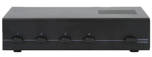
There are ways of connecting multiple speakers to a HiFi amplifier without causing damage, but not by simply connecting one speaker onto the other. For a detailed and practical outline of how to connect four or more pairs of speakers to a HiFi amplifier, see this article. The simple method (with the limitations listed in the other article) is to use a speaker selector switch. A 4 zone switch will allow up to 4 pairs of speakers to be connected to the one amplifier.

Please note, speaker selector switches are designed for multi-room installs in a home or small low power installs (like an office or cafe). They are generally suited for low power (under 100 watts) amplifiers. They should be not be considered in a commercial install or for use with high output power amplifiers.

Speaker selector switches can use various techniques to allow multiple speakers to be connected to the one amplifier, namely:

  • a series resistor (around 2½-5 ohms) to restrict the minimum impedance of the speakers circuit to this value. This simple series resistor is often marketed as “manual impedance protection” or simply “Protection”. They are normally good for lower powered amplifiers, and the resistor can get hot at high volume levels.
  • combining the different speakers in series and/or parallel to keep the overall impedance above 4 ohms.
  • matching impedance transformers – this is normally the best, but it is also the most expensive.

Click here to browse Speaker selector switches available from Amazon

Disclosure: If you buy through this link Geoff receives a small commission from Amazon

All these methods allow multiple speakers, but at a lower volume than using just one speaker. This is logical as the signal is being shared by more than just the one speaker. To see how the power is distributed by the different types of speaker selector switches, see my Speaker Selector Switch Simulator.

For a more detailed explanation and summary of the features of speaker selectors, see my Speaker Selector Switch Summary.

There are also available speaker selector switches which can be controlled through your smartphone or Alexa. Geoff has written a review of the Audioflow series of switches which you can read here.

Instead of using a speaker selector switch to connect multiple speakers to your hifi amplifier you can use impedance matching volume controls, as outlined in the article on connecting four speakers.

Conclusion

Depending on the impedance of your speakers and the rating of your amplifier, you should be able to use two pairs of speakers connected to a HiFi amplifier. However, it is wise to use the example given above as a guide and use the figures in the specifications of your amplifier and speakers to calculate and know for sure what the outcome will be. Otherwise use a multiple speaker selector switch and/or impedance matching volume controls. The video in Understanding Speaker Impedance explains how speaker selectors help with impedance protection

For a practical discussion on how to simply wire just 2 pair of speakers to a stereo amplifier (4 speakers to a stereo amp), see my article on How to connect 2 speakers to 1 amplifier.

For more practical information of how to wire two, three, four or more speakers to one amplifier using speaker selector switches and volume controls, see this article.

Manymultiple speakers -download PDF practical examples of connecting multiple speakers to your HiFi have been discussed in the comments below. If, after reading these discussions, you still have a question please read the FAQs before submitting your question.

Thanks to James from Sydney, Australia who suggested this topic.