Home Blog Page 5

Video Signals & Cables: Component Video

In this article, we look at component video signal: what it is, where it is used, and what cables are used for component video. This is the forth in this series of articles outlining the different video signals used in home entertainment for connecting VCRs, DVDs, set top boxes, cameras and laptops to TVs and projectors. In the previous articles we looked at Composite Video, S-video and RGB video.

“Component video” could well be referred to as “confused video”. Component video is often confused with RGB video in terms of what it is. Component video can be confused with S-video as the luma (picture) and chroma (colour) components of S-video are kept as separate components. Even the phrase “component video” is easily confused with “composite video” during discussions about either. So, lets try to reduce the confusion.

What is Component video?

In the last article we saw how RGB is three coloured picture signals, and the problem is that this is a lot of information to process and store. So when DVDs were invented, they needed a way of preserving the separation of the three coloured signals, and yet reduce the overall amount of information. So instead of having the complete picture for each colour, component video uses one channel/cable to carry the basic black & white picture information (luma). As we saw in the article on S-video, the letter “Y” is used to designate the luma channel. The horizontal and vertical sync (timing information) is also combined in this channel. So the “Y” component is the basic black and white picture bit of component video. To try to confuse you, the Y (luma + sync) component is connected to the green plug and socket of connectors (even though it doesn’t carry any colour information at all – certainly no green).

So all the black & white picture information (luma) is on one channel/cable. Now what about the colour information? This is where it gets tricky. The other channels/cables in component video are called the “colour difference” signals. That is, how much blue and red there is relative to the black & white picture (luma). Mathematically, the blue component is said to be blue minis luma (B-Y), and the red component is red minus luma (R-Y).

So that is component video, just the three channels (cables) are required: Y, B-Y and R-Y. The more astute among you will want to know about the green signal. This is the clever bit: the display (TV or projector) knows how bright the image is (from the Y component). From the B-Y and R-Y components it knows how much of the image is blue and red, so it simply says the rest must be green – simple eh?

To add even more to the confusion, different terms are used to indicate each component. This table tries to make sense of it all.

DescriptionSymbolCable ColourLabel 1Label 2
Luma + SyncYGreenYY
Blue – LumaB-YBluePbCb
Red – LumaR-YRedPrCr

Although there are technical differences between the labels often used for component video, they are generally component Videoused to mean the same thing. So don’t be confused when you see the green, blue and red sockets labelled Y B-Y R-Y or Y Pb Pr or Y Cb Cr. These labels are mostly used interchangeably these days. As in the photo of the back of a DVD player, either type of label may be used, and sometimes both are used.

Where Component Video is Used

Component video is the highest quality analogue video signal commonly used on domestic equipment. It is used extensively on DVD players – indeed the three components of component video are separately stored on a DVD in digital form. Component video is also available from set top boxes, satellite receivers and digital recorders. It can be used for standard definition and high definition images.

Most recent TVs, screens and projectors also have the three component video connectors. Connecting the “component video out” of a device to the “component video in” of a display will give you the highest quality analogue picture available.

Cables to use for Component Video

Red, green and blue cables are most commonly used for component video. Component connection cables for video equipment.The green connector normally connects to the green socket on the sending device (DVD player or STB) and to the green socket of the display device (screen or projector). The “green” channel is normally labelled “Y”, as it is carrying the luma (black and white picture information). The red and blue plugs connect to their corresponding coloured sockets also. The cables use the same RCA (phono) plugs we discussed in the article for composite video.

There is nothing magical about the colour of the plugs and sockets. The colours are there simply to make it easy for you to connect each component of the component video from the sending device to the correct input of the display device. If you have other coloured leads, you can also use them – just make sure you connect the “Y” signal out to the “Y” signal in, and the same for the red and blue difference signals. If need be, you can even use the yellow, red and white composite video (and audio) leads for component video over short distances – just make sure the right output component video signals are connected the their respective inputs of the display device.

If the cables are not connected correctly, there is normally no damage done, but the colour of the image will be wrong. Obviously, if the “green” (Y) only is connected, you only get a black & white image. If the “red” and “blue” cables are swapped, the colours will simply be wrong (as the red and blue colour information is swapped). If the “green” is not connected correctly most displays will indicate “no signal” as it can’t detect the basic picture.

Good quality cables are required for component video, especially over longer distances. As mentioned in the article on composite video, good quality RG59 video cable can be used for lengths up to 100 metres (300 ft).

Video Signals & Cables: RGB video

In this article we look at RGB video signal: what it is, where it is used, what cables to use and the problems with RGB video. This is the third in a series of articles outlining the different video signals used in home entertainment for connecting VCRs, DVDs, set top boxes, cameras and laptops to TVs and projectors. In the previous articles we looked at Composite video and S-video.

What is RGB video?

In a black & white video camera the image comes through the lens and onto the sensor 
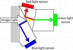
which generates a video signal representing the image. In a colour video camera, after coming through the lens the signal is split into three different colours (red, green and blue) through prisms. These coloured images then each go to a separate sensor, generating three separate video signals, one with the red picture information, one with the green picture information, and one with the blue picture information.  These three separate video signals (Red, Green and Blue) is what is known as RGB video. It is the most pure form of analogue colour video signal.

As well as the three full coloured signals, there also needs to be the timing information to make up picture. We need to appreciate that although a TV picture looks like it is a continuously moving picture, it is actually a series of still pictures (called frames) changing 25 or 30 times a second – and this looks like a continuously moving picture to our eyes. Each frame (still picture) is made up of lots of horizontal lines (525 or 625 lines). All these lines and frames need to be kept in time, or in sync, hence these timing signal are called horizontal sync (H) and vertical sync (V).

Some RGB video signals combine the sync signal with the green coloured picture and some have separate cables for each, requiring 5 signal paths in total.

Where RGB Video is Used

In many countries, RGB video is not used a lot with domestic equipment.

SCART comes from Syndicat des Constructeurs d’Appareils Radiorécepteurs et Téléviseurs. The plugs have 21 pins and allow RGB video, S-video and composite video (along with left and right audio). They are also know as Péritel, 21-pin EuroSCARTEuroconectorEuroAV and EIA Multiport.

The exception is in Europe, where SCART leads are used for connecting between DVD players, Set top boxes and displays.

A number of DVD players are capable of delivering RGB video at their output, but you normally have to enable this in the setup menu. However the display you are connecting to also needs to be able to received RGB video – this is not very common.

Where RGB video is commonly used, is when connecting a laptop to your display. Most flat screens and projectors will accept RGB, with seperate H and V sync (timing signals), referred to as RGBHV. This is the type of RGB video signal available from many computers.

SCART plug
Cables to Use for RGB Video

Scart connectors are widely used in Europe. They are convenient as the video and audio are connected through the one plug, reducing the confusion from having to plug in three video cables and two audio cables.

RGB video VGA plug
VGA Plug

The standard VGA (Video Graphics Array) plug has been used to connect computers to monitors for many years. They have 15 pins and carry the three RGB coloured signals and separate H sync and V sync. This is the best quality analogue colour signal that a computer can produce. VGA is now the generic term used for this type of plug and cable – it was originally introduced by IBM.  Good quality VGA cables can be run up to 50 metres (150 feet). Longer cable runs can use 5 seperate RG59 coax cables. Note: VGA cables only carries video signals, separate cables are are required for audio.

Problems with RGB Video

RGB video may well be the purest form of analogue colour video available, but it is a lot of information to be processed and stored. Remember it is three complete picture waveforms. Therefore it is not easily stored, especially by domestic recorders.

In the next article, we will discuss component video, and see why it is often used in domestic and commercial AV installations.


Video Signals & Cables: S-Video

In this article we look at S-video signal: what it is, what cables to use, where S-video is used and the problems with it.  This is the second in the series of articles outlining the different video signals used in home entertainment for connecting VCRs, DVDs, set top boxes, cameras and laptops to TVs and projectors. In the previous article we looked at Composite Video.

What is S-Video?

S-Video is an improvement on Composite Video as the luma and chroma stay separated. S-Video was introduced with Super VHS Video Cassette Recorders as these higher quality devices recorded the luma and chroma separately on to the video tape. This overcame the problem of having to separate these two components in the TV, as they were already separated (they were not mixed in the first place). By keeping the luma and chroma separate throughout the whole signal path, the resulting picture appears crisper with less colour smear compared to composite video.

The “S” in S-video normally means “Super” video (like Super VHS) or “Separated” video. In a S-video signal, the sync (timing information) is still combined with the luma information. In technical articles, the luma signal (black & white picture information) is represented by the letter “Y”. Chroma (the colour information) is represented by the letter “C”. Hence S-video can also be referred to as Y/C video signal.

Cables to use for S-video

S video connector

s video connector

The normal connecter for S-Video uses 4 pins: 2 pins for “Y” (luma) and 2 pins for “C” (chroma). The cable needs to have two separate pairs (4 wires in total). Pre-made S-video cables are normally available in lengths up to 15 metres (50 foot).  For longer cables, it is normal to use a breakout cable at each end, and install two RG59 video cables in between.

Please be careful when using a S-video plug, make sure it is orientated the right way as the pins are easily bent if forced in the the wrong way.

Click here to browse S-Video leads available from Amazon

Disclosure: If you buy through this link Geoff receives a small commission from Amazon

Some devices also use a 7 pin socket. A 4 pin S-video plug should plug into a 7 pin socket with the 4 pins connecting to the right sockets containing the luminance and chroma signal.

Where S-video is Used

S-video is not regularly used these days as there are better ways to connect video signals. However it is still widely available on many DVD players, Set Top Boxes (STB) and game consoles. Older laptop computers also have a S-video connector (although often 7 pin).

To connect a screen or projector with a S-video cable, it needs to have a S-video socket, as does the DVD player or STB.

Problems with S-video

Although S-video is better than composite video in that the chroma (colour) and luma (picture content) are separated, there are still problems with S-video. Colour content for video is made up of red, blue and green. In S-video, all this colour information is combined into one signal path and cable and is therefore compromised.

In the next articles we look at RGB video signals, and then component video, where the colour information remains separate.


Phone & Ipod Chargers


Do phone chargers and Ipod chargers draw power when not connected to their device? The answer is: it depends on the type of charger.

There are two basic types of technologies used in power supplies (a charger is basically a power supply). It is useful to have a general understanding of the two types of power supplies. So, without getting into the technical issues, the two technologies are:

1) Transformer Power Supplies

Transformers have been traditionally used in power supply designs for many years. A transformer transforms high AC voltage to low AC voltage. Then some simple circuitry changes the AC to DC.

2) Switch Mode Power Supplies (SMPS)

Switch mode power supplies are a newer technology. They convert the AC to DC, then switch the DC on and off very quickly at different rates to produce the required voltage.

Differences

The major differences are outlined in the table below.

Transformer Power SupplySwitch Mode Power Supply
Produce heat even when not used, so are less efficientProduce little or no heat when not used
Have a heavy transformer in themDo not have a heavy transformer
Have a narrow or fixed input voltage (like 230-240 volts)Can have a wide input voltage (like 100-250 volts)
Draws some power even with no loadDraws negligible power with no load

So it is simple to tell which type of power supply your phone or Ipod uses for its charger. If it is warm when not connected, has very limited input voltage range (read the label) and feels a bit heavy for its size, then it is probably a transformer power supply.

If it doesn’t get warm when not connected, has a wide input voltage, and feels like there is nothing in it, then it is probably a switch mode power supply.

So, does your charger draw power when not plugged into its device? The above table gives some hints to this answer. In practical tests, I cannot measure the power drawn by my switch mode power supply phone charger when not plugged into my phone, as it is too low for my power meter to read. It did draw about 4 watts when connected to the phone and charging. It reduced to 2 watts once the phone was charged.

On the other hand, when I measured the power drawn from a transformer power supply, it measured 3 watts with nothing connected to it.

I want to thank Mark from Canberra, Australia for asking this question. I hope this helps you understand and use your technology better.

The Cost of Standby Power

In the popular press there have been a number of reports along the lines of “households wasting hundred of dollars on standby power”. Being an inquisitive sort of fellow, I bought a simple power measurement meter to see how much money was being wasted in our home.

After some time measuring all the electrical appliances in our home, I sent the following letter to the editor of “Silicon Chip” magazine and it was published in the November 2011 edition:

It has been an interesting exercise to tabulate the various consumption figures of all our devices when they are on and off. I then made up a quick spreadsheet so I could see the annual costs rise and fall as I changed the usage time.

The surprising discovery in all this has been how little power modern appliances seem to use on standby. The following costs are based on 24 hour connection and 24 cents/kWh.

32″ LCD TV0.4 watts$0.84 per year
STB/PVR1.1 watts$2.31 per year
DVD player0.5 watts$1.05 per year
22″ LCD Monitor0.7 watts$1.47 per year

These figures seem to line up with what I believe is the European standard which requires a standby power usage of less than 1 watt to be considered “green”.

Some of the older appliances used more power on standby:

Masthead amp3.2 watts$6.73 per year
CRT TV5 watts$10.51 per year
VCR6 watts$12.61 per year
modem/router5.5 watts$11.56 per year
Mircowave3.1 watts$6.52 per year

Even at these figures, you would need several old TVs and VCRs to make up the hundreds of dollars the popular media tell us we are wasting with standby power each year. Certainly turning off computers, CRT monitors/TVs and VCRs when not in use can reduce the power bill a bit. Of course turning off 3 x 50 watt downlights for an hour, or a 2400 watt heater for 4 minutes, will save more than leaving the VCR in standby for 24 hours – and you wouldn’t need to reset the clock.

The other thing I observed is a useful rule of thumb formula. At 24cent/kWh (the cost according to the bill I got last week), it is simply a matter of doubling the standby watts, to give you the cost per year. For example, a TV with a standby power of 5 watts, will cost just over $10.

The point being, modern appliances do not draw much power when on “standby” (turned off but still connected to the power). Older appliances do use slightly more power on standby, but you would need a lot of them to make up the “hundreds of dollars” often mentioned.

Of course, even little amounts do add up, so if you are not using something every day, you will save power by turning it off at the power point on the wall (or the switch on a power board) .

However if your TV and DVD player are made in the last few years, it will only cost you a few dollars a year if you leave them in “standby” while not being used. For this price is it not worth the effort I’ve seen people go through to reach in behind their entertainment system and flick the power switch off each night.

I find it much easier to turn off lights and appliances (like heaters and air conditioners) when no one is the room, and this does save power. In the last quarter alone, our electricity bill dropped by $160 by using electrical things less – and my entertainment system is still turned on.

If interested, you can easily calculate your own power usage for each appliance with my Power Usage Calculator.

Click here to browse simple power meters available from Amazon
Disclosure: If you buy through this link Geoff receives a small commission from Amazon

Using a Multimeter

24

This article introduces the basic concepts of multimeters and explains how to use them for basic measurements. Multimeters are one of the most useful electrical and electronic aids available to us. Effectively they are our eyes to see electricity. The ability to use a multimeter is essential if you need to know what is going on electrically. A multimeter is, as the name suggests, a meter capable of multiple functions. A basic meter will allow us to measure and test AC voltages, DC voltages, DC polarity, resistance and often current. More advanced meters also measure frequency, capacitance, transistor gain, and/or inductance.

Analog vs Digital Multimeter

Multimeters come in many shapes and sizes. However there are basically two types:

The basic differences are outlines in the following table:

Analogue metersDigital meters
1. Indicate with a pointer that moves across the face of the meter.1. Display the measured value in actual digits (numbers).
2. Not as accurate as a precisely calibrated digital meter.2. Normally regarded as more accurate than analogue (only if they have been correctly calibrated).
3. Can require some practice to quickly read exact voltages, although they are very useful in showing that a voltage is present.3. Easier to read exact values than on analog meters. However this is often an over kill when all you need to know is if a voltage exists or not.
4. Especially suited to measuring voltages that vary quickly. The pointer closely follows the voltage as it varies up or down quickly.4. Display misleading results if the measured voltage varies quickly. This is because most digital meters require a second or more to read the measured voltage. If the voltage varies greatly during this time, then the reading will be wrong.
5. Only require a battery when measuring resistance.5. Require a good battery to work on all settings.


If you don’t own a meter, or cannot readily borrow one, then it is time to invest in one. A basic meter will probably be adequate for your needs. That is one that simply reads AC and DC volts, resistance and DC current. The choice between analogue and digital is yours, and will depend on availability as much as your budget and preferences. It is not recommended to pay too much money for your first multimeter, as your use of it may not be justified. However a meter that does the basics is very usful.

Click here to browse simple power meters available from Amazon

Disclosure: If you buy through this link Geoff receives a small commission from Amazon

Digital meters are commonly available in most electronic stores. Analogue meters are often regarded as “old technology”. However in many situations an analogue meter may be the only meter available that is working (since they don’t require batteries to read voltages). Both types of meters will be discussed in this chapter. If you have a meter, please have it with you as you read this article. Read the instructions for your particular meter to be aware of its functions. Where possible use your meter to do the exercises as practical examples.

Measuring Voltages on your Multimeter

No matter what sort of meter you have, you need to know roughly what sort of voltage you are measuring. The first choice is between AC and DC. As a guideline, common sources are:

For AC:   transformers, alternators (often erroneously called generators), house wiring, light sockets, power outlets (wall sockets).

For DC:  batteries, solar panels, cars, electronic equipment.

Once you have determined if you will be measuring AC or DC, you need to select this on your multimeter. Refer to your meter instructions. Most meters will not be damaged by selecting AC instead of DC, or DC instead of AC. However the meter won’t read correctly, if at all.

The next step is to consider roughly the magnitude of the voltage you will be testing. Then select on your meter a range that is bigger than that voltage.

Example 1: You want to measure the voltage at the wall outlet. It should be 220 or 240 volts, select the 250 or 300 volts range on AC.

Example 2: You want to measure the voltage of your car battery. It should be 12 volts. Select the 15, 20, 25, 30 or 50 volt range on DC, (depending on your meter’s ranges).

If you are not sure what the voltage should be, then start on the highest range.

Analogue Meter
Digital Meter
If the meter pointer only moves a tiny bit, then select a smaller range. Continue to select a smaller range until the pointer is midway or higher.If the readout reads 0.01 or a similar very low reading, select a lower range until a more meaningful reading is displayed.
If the pointer goes off the scale (all the way over the right-hand side) then you need to quickly remove the probes, select a higher range, then measure againIf the range selected is too high, most meters will display OL or -1 or similar indicating overload or out of range.


Some (more expensive) digital meters have a feature called “auto-select” or “auto-ranging”. This means that the meter will automatically select the appropriate range for the voltage you are measuring. With these meters, all you need do is select AC or DC.

WHICH PROBE WHERE?

Every meter has two probes. One black probe and one red probe. The black one is generally connected to the negative(-) or common terminal of the meter. The red probe is generally connected to the positive(+) terminal of the meter.
[warning]

To avoid electric shock when measuring voltage or current, always hold only the plastic insulation on the probes.
DO NOT touch the metal pins

Measuring AC

When measuring AC, it doesn’t matter which probe goes to the phase (sometimes known as “active” or “hot”), and which probe goes to the neutral (sometimes known as the “cold”. That is, AC has no polarity (see the article on AC and DC  for more details).
Exercise 1: To measure the voltage at a wall outlet, insert one probe in one hole and the other probe in the other hole. It doesn’t matter which probe goes where. Try it with your meter:

  1. Select AC volts, 250 or 300 volts range (depending on your meter’s ranges).
  2. Being sure not to touch the metal points of the probes, put one probe in one of the holes in the wall outlet. Put the other probe in the other outlet hole. Your meter should read somewhere near what the voltage should be (110, 220 or 240 volts).
  3. Now, still being sure not to touch the metal points of the probes, swap the probes over. That is, remove both probes from the outlet holes, swap them over and carefully re-insert them. Your meter should read the same as it did before. This shows it doesn’t matter which way the probes go when measuring AC.

Measuring DC

When measuring DC, you need to put the red probe to the positive(+), and the black wire to the negative(-) of the voltage being measured. If you mix this up and reverse the wires, then the meter will read backwards. That is, on analogue meters, the pointer will quickly move off the left-hand side of the scale. If this happens, no permanent damage normally occurs, simply reverse the way you have the probes. On digital meters, all that happens is that a “-” sign appears in front of the numbers indicating a negative voltage.

Exercise 2: To measure the voltage of a car battery.

  1. Select 15, 20 or 50 volts DC on your meter.
  2. Place the red positive probe on the battery positive terminal.
  3. Place the black negative probe on the battery negative terminal.
  4. A good battery should read between twelve and fourteen (12-14) volts.

A common use for a multimeter is to detect which lead from a battery or power supply is positive and which is negative. When you don’t know which is which, hold one probe on one of the leads to be tested, and then momentarily touch the other lead with the other probe. If, on an analogue meter, the pointer moves off to the left, then swap the probes over. When the meter reads correctly, the red probe is connected to the positive wire (or positive battery terminal). On a digital meter, if the “-” sign appears, then reverse the probes for the red lead to be connected to the positive.

Exercise 3: Detect the positive end of a small flashlight battery.

Analogue MeterDigital Meter
Ensure the red probe is connected to the positive terminal of the meter.Ensure the red probe is connected to the positive terminal of the meter.
Select DC volts, and the 3 or 10 volts range (or whatever your meter has).Select DC Volts, and the 2 volts range (or whatever your meter has).
Connect the black lead to either end of the battery. Momentarily touch the red probe against the other end of the battery.Connect the black lead to either end of the battery. Touch the red probe against the other end of the battery
If the meter reads correctly, go on to the next step. If the pointer moves off to the left, change the probes around. That is, connect the black probe to the end you just momentarily touched with the red probe. Now touch the first end with the red probe. The meter should now read correctly.If the meter reads correctly (i.e. no “-” sign), go on to the next step, if a “-” sign appears, change the probes around. That is, connect the black probe to the end you just touched with the red probe. Now touch the first end with the red probe. The meter should now read correctly
The end connected to the black probe is the negative(-) wire. The other end is positive(+).The end connected to the black probe is the negative(-) wire. The other end is positive(+).


 Practical points to Note

1) The meter reads the voltage between the two probes, not necessarily the total voltage in the circuit. This may seem like a logical statement, but many people have been trapped by not understanding the difference.

2) Looking at the output voltage of a HiFi amplifier is best done with an analog meter.

Exercise 4: It doesn’t matter if you use the left or right channel, but you need to use the positive and negative terminal of the one channel.

  1. Select AC and the 50 volt range on your meter.
  2. Connect one probe to the negative speaker terminal.
  3. Connect the other probe to the positive speaker terminal.
  4. The meter pointer should dance up and down in time with the music. How far the needle moves will depend on the volume control.

This is not a very practical way of measuring the output, but it does give an interesting display. To properly measure the output capabilities of your HiFi amplifier you need other test equipment.

Measuring Resistance on your Multimeter

A useful feature of multimeters is their ability to measure the resistance in a circuit. Although the exact resistance in a circuit may not be useful to you, often knowing the relative resistance is. Example: Knowing the exact resistance of your clothes iron isn’t important. However knowing that there is some resistance (that of the heating element) tells you that it should work. No resistance indicates a broken connection which needs to be fixed.

The best way known to destroy your meter is to try to measure high voltage (like 220 volts AC) while still on the resistance range.
Always ensure the power is turned off and disconnected before measuring resistance

The method of setting your multimeter for measuring resistance is different for analogue and digital meters. Therefore, we will look at each separately.

 Analogue Multimeter    Digital Multimeter
1. Select resistance. This is often signified by the Ohms symbol “Ω”.1. Select Resistance. This is often signified by the kilo-Ohms symbol kΩ.
2. Calibrate the meter. To do this locate the “Ohm’s Adjust” knob, a small control like a volume control. Hold the metal points of the black and red probes together so that they touch each other. While they are still touching, move the “Ohm’s Adjust” control until the needle aligns with the far right-hand side of the scale. This should be “0” on the ohms scale (normally the top scale).2. Digital meters are pre-calibrated so no further calibration is required
3. Place the probes across the resistance to be measured. For most resistance measurements it doesn’t matter which probe goes where – that is, it is not polarity conscious3. Place the probes across the resistance to be measured. For most resistance measurements it doesn’t matter which probe goes where – that is, it is not polarity conscious
4. Read the number of ohms from the meter. The top scale usually is the scale to read for resistance. Assume the needle is pointing at “15”. If the range was Ω x 1, then you are measuring 15Ω. If the range is Ω x 10 then you are measuring 150Ω. Likewise Ω x 100 = 1500Ω and Ω x 1K = 15,000Ω or 15kΩ. If the needle is close to the left-hand side of the scale, select the next range.Example: the range is on Ω x 1. The needle is pointing at 1200. Change the range to Ω x 10 for the needle to point at 120.4. Read the number of ohms from the meter. The numbers displayed indicate the resistance in Ohms. Digital meters usually measure in Kilo-ohms (KΩ). Therefore if the meter is showing 1.5, it means 1.5KΩ, or 1,500Ω, not 1.5Ω. Take note of the little symbols indicating the range (if displayed). This is especially important on “auto-ranging” meters. Without noting that it is Ω, KΩ or MΩ you can easily be mis-led into a false reading
5. If the resistance in the circuit being tested is very high, or no circuit at at all, then the needle won’t move. That is, the needle stays on the left-hand side of the scale, showing infinitive(∞) ohms5. If the resistance in the circuit being tested is very high, or no circuit at all, then the meter will try and tell you. There are various ways to indicate this condition. Some display OL, meaning “Open Loop” or “Over Load”. This means the resistance is so high it is considered to be no circuit at all, or at least outside the range of measurement. Some meters flash 1.999 to indicate this condition.Check to see what your meter does with both leads unconnected.


Some common terms

Short Circuit: When there is zero resistance in the circuit, it is said to be a “short” circuit. This is shown on all meters by reading “0” (zero ohms) – or close to zero ohms.

Open Circuit: When there is so much resistance that the meter can’t register it, it is said to be “open” circuit. This usually indicates that there is no connection between the probes.

Note: When there is an open circuit, the meter can sometimes suggest some resistance (often measured in Mega-ohms). This is normally caused by touching the probes with your hands, and the meter is actually measuring your skin resistance.

Practical Uses of Measuring Resistance

As mentioned earlier, knowing the exact resistance in a circuit is often not as important as knowing if there is a circuit at all, if there is a short circuit, or if there is an open circuit. Try the following exercises as examples.

Exercise 5: Test a lead to see if it is faulty or not. This could be a lead from your HiFi, a power extension lead or a microphone lead.

  1. Select Resistance and the Ω x 1 scale. If using an analog meter, calibrate it to read 0Ω when shorting the probes together.
  2. Check the lead for short circuits. Using only one end of the lead, place a probe on each connection. Your meter should read infinitive resistance, saying there is no circuit between the two probes. If your meter shows close 0Ω, (a short circuit), then it needs to be fixed or replaced. The most common places for “shorts” to appear are in the plugs at either end.
  3. Check the lead for continuity. Using both ends of the lead, place one probe on the same point at each end. Your meter should show a short circuit (0Ω). Now do the same for the other connection on each end. If on either connection you do not get a short circuit, then there is not a continuous circuit in the lead where there should be. It probably means the lead is broken. The normal way to fix this is to cut 10cms off either end of the lead, check that the lead now has continuity, and then rejoin the connecters. This is recommended because the greatest wear on the lead is where it bends at the exit of the plugs. If after replacing the ends there still is no continuity then it is probably best to replace the lead.

Note: Some stubborn leads will only show an open circuit after bending the lead severely at either end. This suggests the lead is broken but still making intermittent connection. It also should be cut shorter and re-joined.

Exercise 6: Check a light bulb to see if it is OK. If a flashlight doesn’t work it is good to know if the batteries are flat, if there is a bad connection or the bulb is blown.

  1. Select resistance and the Ω x1 range. If using an analog meter, calibrate it to read 0Ω when shorting the probes together.
  2. Place a probe on each connection on the light bulb. Your meter should show a circuit. Often it shows the resistance is almost zero ohms, this is normal and suggests a good light bulb.

Note: the resistance of a light bulb increases greatly when power is applied. This is because, as with most resistances, the resistance increases with temperature.

If the light bulb checks out OK, select DC volts on your meter and check that the batteries are also OK.

Exercise 7: Check if a fuse is blown or not. If you think a fuse is blown, the best way to know for sure is to remove the fuse (with the power off!) and test it with your multimeter.

  1. Select resistance and the Ω x1 range. If using an analog meter, calibrate it to read 0Ω when shorting the probes together.
  2. Place a probe on each end of the fuse. Your meter should show a short circuit (no or very low resistance). If there is very high or infinitive resistance, then the fuse is blown.

Measuring Current on your Multimeter

Most multimeters have the facility to measure small amounts of DC current. Some meters also allow the measurement of AC current. Although the measurement of DC current is explained here, the procedure for AC current follows similar principles.

When we measure voltage, we are measuring the difference in voltage from one probe to the other. That is, we measure the voltage across a particular resistance.

Example: Here we have two 1.5 volt batteries connected in series to give 3 volts across the resistance (a light bulb). By placing the probes as shown we can measure the voltage (3 volts) across the light bulb.

To measure the current in a circuit we need to measure the current flowing through the resistance. We have seen that we can’t simply place the probes across the resistance, as this gives us the voltage not the current. So what is the secret?

In the article on The Dreaded Ohms Law, we learned that the current flowing through a series circuit is the same throughout the whole of the circuit. Therefore if we can measure the current flowing through any part of the circuit, we are effectively measuring the current flowing through the resistance. That is, the current flowing through the resistance is the same as the current flowing through the wire, which is the same as that flowing through the batteries (to use our example).

So how do we do all this? We could cut the wire between the battery and the light bulb. Then connect one probe to each of the cut ends, with the multimeter selected to measure DC current. This would work as we are measuring the current flowing through the wire (and the multimeter). Because it is a series circuit, we are also measuring the current flowing through the light bulb and the batteries.

However it is not always wise to cut wires unnecessarily. In our example, an obvious place to break the circuit and insert our probes would be at the end of one of the batteries. Most battery holders have a spring to help make a good contact. It is normally possible to separate the batteries and insert a small piece of cardboard to isolate the batteries from each other. Then it is a matter of simply placing a probe on either side of the cardboard.

Whichever way it is possible to break the circuit, it is at that point that the probes need to be inserted.

Which probe where?

When measuring AC current, it doesn’t matter which way the red and black probes go. On DC it does matter. The black (negative) probe should go on the positive side of the break. That is, it should go on the side of the “break” that is closest to the positive of the power supply (or batteries). If you mix this up and reverse the wires, then the meter will read backwards. That is, on analog meters, the pointer will quickly move off the left-hand side of the scale. If this happens, no permanent damage normally occurs, simply reverse the way you have the probes. On digital meters, all that happens is that a “-” sign appears in front of the numbers indicating a negative current, but the value is correct.

Practical Points to note

1. When measuring AC current (if your meter has that selection), be very careful not to touch the metal points of the probes.This is because most often when measuring AC, it is at dangerous (high) voltages.

2. Beware of your meter’s limitations. Many meters only allow the measurement of very small DC currents. Often 25 milli-amps(mA) is the maximum. Many meters also have the capacity to measure 10 Amps. To do this you normally need to move the red probe to a different socket on the meter. This is often 10 amps AC only, not DC. Be sure to read the manual closely to know what you meter can and can not do.

3. Many digital meters allow a maximum of 200mA. If this limit is exceeded, a fuse in the meter will probably need replacing. It is wise to have a good stock of replacement fuses on hand.

4. Inserting the probes between two batteries is an easy way of checking the charging current being delivered to Ni-Cad batteries.

SUMMARY

To avoid electric shock when measuring voltage or current, always hold only the plastic insulation on the probes.
DO NOT touch the metal pins

When measuring AC, it doesn’t matter which way the probes go.

When measuring DC voltages, the red positive probe goes to the positive side of whatever is being tested.

When measuring resistance, ensure there is no power applied to the resistance being tested. It doesn’t matter which way the probes go.

When measuring current, it is necessary to break the circuit in an appropriate place and insert the probes in series with the circuit under test. The black probe goes to the positive side of the break.

So there you go, grab a multimeter and start “looking” at electricity – but do it carefully!

AC and DC

0

This article looks at some basic concepts and misconceptions of AC and DC electrical circuits. There are no formulas involved, just explanations to some commonly asked questions like:

What is AC and DC? What are their differences and what does it matter?

If AC follows a “sine wave” pattern, how do we measure the voltage when it is always moving up and down?

What is “peak power” as apposed to “RMS Power”?

Which way does current flow in a circuit, especially in AC?

What is 3 phase electricity all about?

What does “3 phase, 50Hz, 380 volts” means?

As an introduction to looking at these concepts, mentally picture the following experiments (you can actually do them if you like – they are not difficult).

If you were to measure the voltage from a flashlight battery and plot this voltage every second on a graph, I trust that you would get a result similar to this:

That is, a straight line indicating 1.5 volts continuously (the line would slowly drop slightly from 1.5 volts as the battery went flat).

Now if you were to switch the positive lead to the negative end of the battery, and the negative lead to the positive end of the battery, that is, switch it all around, then you should get a result like this:

This is similar to the first graph, but upside down because it is negative.

Now if you were to quickly switch the leads back and forth, you should end up with something like this:

That is, the voltage is continually going positive, then negative, then positive, and negative again. In other words it is alternating from positive to negative. Hence this alternating nature is commonly called Alternating Current or the shortened form is simply AC. The word current here is used generically, that is although we use “current”, it also relates to the voltage and power.

The converse of Alternating Current, is Direct Current. DC refers to whenever the voltage isn’t alternating between positive and negative, but stays either positive or negative, as shown in the first two graphs. Note that DC can be positive or negative.

AC

Changing a battery around quickly isn’t a very practical way of producing AC. The most common way is by using an alternator (sometimes called a generator, although strictly speaking a generator produces DC, whereas an alternator produces AC).

Other devices that also produce an AC signal are: radio transmitters, inverters and audio amplifiers (e.g. HiFi amplifier).

Let’s consider the voltage produced by an alternator:

This “sine wave” pattern is the path followed by current, voltage and power in an AC circuit. It doesn’t stay positive or negative for very long, neither does it stay at one particular level. Which begs the question: “How do we measure AC? When we say we have 220 Volts 50 Hz, what does it actually mean?” Let’s look at the 50 Hz part first, as it is the easiest to understand.

Frequency of an AC circuit

The frequency of an AC circuit is simply the number of complete cycles of the wave in one second. This measurement of frequency used to be called “cycles per second” or cps, but these days is called Hertz (Hz) after the German scientist involved in AC circuits.


That is:

           One Hertz  = One Cycle per Second
             1,000 Hertz (1kHz)  = One thousand cycles per second
 1,000,000 Hertz (1MHz)  = One million cycles per second

Let’s look at some examples of this:

Example 1: 220 Volts 50 Hz means the voltage goes positive, then negative (one cycle) 50 times a second.

Example 2: 110 Volts 60 Hz means the voltage has 60 full cycles per second.

Example 3: When BBC radio transmits on 15.420 MHz, it means the transmitter is producing complete cycles of AC 15,420,000 times every second.

Example 4: BBC TV satellite broadcasts into Europe use a frequency of 10.995 GHz (Giga Hertz). That is 10,955,000,000 cycles per second!

PRACTICAL POINTS TO CONSIDER

1. In most circumstances it doesn’t hurt to use an appliance on either 50Hz or 60Hz. That is, if a toaster is designed for 110 volts 60Hz, you can use it on 110 volts 50Hz with no apparent difference.

2. AC motors are an exception to the above point. The speed of an AC motor is dependant on the frequency of the supply (an AC motor which has brushes e.g. a portable drill, is not governed by frequency – this class of motor is known as an universal motor, not strictly an AC motor). An AC motor turns faster on 60Hz than on 50Hz. This doesn’t normally worry the motor, but it may affect the performance of the equipment it is connected to. It can also affect the cooling efficiency of the internal fan of the motor.

Example 1: A printing press designed for 60Hz will work fine on a 50Hz supply, but will run 20% slower. Also a supplementary fan may be needed to help cool the motor.

Example 2: A 60Hz photocopier that uses an AC motor to transport the paper through it may not work at all on a 50Hz supply. This is because it transports the paper at a reduced speed, which allows the photocopier to think it has jammed paper, therefore it stops and indicates “paper jammed”. The only remedy is to use it on a 60Hz supply (like a generator).

3. Transformers can be used on either 50Hz or 60Hz without any problem. Often a 220volt/110volt transformer is used to allow a 110 volt 60Hz appliance to be used on a 220 volt 50HZ supply.

Voltage of an AC Circuit

Although here we talk about voltage, the same principles also apply to current and power in an AC circuit.

Earlier, we saw that in a DC circuit (a battery) the voltage was a constant 1.5 Volts – pretty simple to measure. However in an AC circuit, the voltage is going from zero volts, reaching a positive peak, falling back to zero, reaching a negative peak and returning to zero again, many times a second. So at what point do we measure it?

If we measured the peak voltage only, then that would be a little misleading, as the voltage is only at this peak level for a fraction of the cycle. Therefore we need to measure it at a point that is sort of average over the whole cycle.

This is basically the effective working voltage, in reality 0.707 of the peak. Officially this is called the RMS of the sine wave. RMS stands for Root Mean Square, which is the mathematicians way of saying 0.707 of the peak, or the effective working voltage

In practice, it is the RMS value that meters are calibrated to read.

Therefore, when you measure 220 Volts on your meter, the peak of the voltage is actually 311 Volts. The peak-to-peak voltage is 622 Volts!

The following chart shows these relationships for common voltages (values rounded off).

RMS ValuePeak VoltagePeak-to-Peak Voltage
110155311
120170339
220311622
240339679


PRACTICAL POINTS TO NOTE

1) A meter reading might deceive you into thinking that a voltage is safe to touch (a very dangerous practice), when in fact it is much higher.

2) A SSB radio transmitter (as used by people to speak long distances) might be rated at 100 Watts PEP. The PEP stands for Peak Envelope Power, which is basically equivalent to Peak-to-Peak. This is the normally accepted method of measuring transmitter power, not RMS. SSB radio transmitters are the only exception, normally all figures should refer to RMS.

3) The power of an audio amplifier should be quoted in watts as “continuous”, “Average” or “RMS”. Beware of advertising which boasts “100 watts peak power!”. Close scrutiny reveals that the RMS value (effective working power) is only 17.5 Watts. Firstly divide the 100 by 2 because it is stereo (100/2 = 50 Watts). Then divide this by two to get peak value from peak-to-peak (50/2 = 25 Watts). Then 0.707 of 25 is 17.5 watts. For more info on Amplifier Power see the article Understanding Amplifier Power.

Calling a 17.5 watt stereo amplifier a 100 watt one, is similar to saying the voltage at the wall outlet isn’t 220 volts, but 1866 volts! That is, the peak to peak voltage times three (for three phases) – slightly absurd.

Changing AC to DC

AC is used in distributing electricity for 2 main reasons:

1) It has less voltage losses than DC, i.e. it is a good way of delivering electricity over long distances through wires because it doesn’t loose as much voltage as DC would.

2) It is easy to change the voltage (using a transformer)

However, apart from motors, heaters and lights, most appliances (especially electronic appliances) use low voltage DC. For example: MP3 players, radios etc work on 3, 5, 6, 9 or 12 Volts.

The best source of pure DC is a battery or a group of batteries (in series) to make up the appropriate voltage. However batteries go flat. That is why most electronic appliances have provision to be run from the AC supply also. It is the job of a power supply to change AC to DC.

Simple power supplies are reasonably cheap. They are often known as “plug-packs”. These are used to power or charge Mobile phones, MP3 players etc. They change AC to DC and often allow different voltages (e.g. 4.5 volts, 6 volts, 9 volts and 12 volts).

Note: Power supplies are designed for certain voltages and certain currents. Be careful not to draw more current than they are designed for.

Current Flow in AC and DC Circuits

Every circuit needs 2 wires: one to carry current into the circuit and one to carry the current out, or to return the current to the source (battery, alternator etc). It is useful to always have the on/off switch in the wire that carries the current to the circuit. Therefore, for this and other reasons, it is good to know which way the current flows in a given circuit.

Unfortunately there is a lot of confusion over which way current flows in a circuit. This confusion has predominantly been raised in technical arguments, most of which have merit. However let us simply use the practical and generally held view that current flows from positive to negative.

In a DC circuit, this is easy to visualise, however what happens in an AC circuit when it is constantly going from positive to negative to positive? An analogy might help: A down hill snow skier is constantly going right – left – right, but still continues in one basic direction. Similarly, even though AC is going positive – negative – positive, basically it is going in one direction. It is easier to use the term “active”, “hot” or “live” for the wire carrying the AC, and the term “neutral” for the return path wire.

Thus we can say in an AC circuit, the current flows from active to neutral.

Three Phase AC

Three phase AC is a very common output from alternators. It is also an engineers delight, when it comes to explaining it. Which is as good a reason as any why we won’t detail it too much. Suffice to say that from the one alternator, 3 separate but related sine waves (phases) are produced (120° out of phase from each other).

It is the relationship between these 3 phases and the neutral that interests us. The basic principle is: Between any 2 phases is one higher voltage, between any phase and the neutral is a lower voltage.

The following table details this relationship for some common voltages.

Between any phase and neutralBetween any two phases
110 volts190 volts
120 volts208 volts
220 volts380 volts
230 volts398 volts
240 volts415 volts


In many countries the supply authority provides 3 phases to each house. When this is done, each phase can be regarded as a separate supply line. That is, the three phases can be regarded as three separate and individual supply lines. Instead of wiring all your house on one single phase. It is often advantageous to spread the load over 2 or 3 three phases.

The advantages of sharing the load over two or three phases are many. The greatest is that you are not dependant on the supply authority to provide good voltage on one phase alone.

PRACTICAL POINTS TO NOTE

1) Three phases and a neutral (4 wires) are often supplied to houses. The two wires for lights and appliances, are connected to any one of the phase wires and the neutral wire, never to 2 phase wires.

2) If the neutral wire is replaced with a phase wire (i.e. accidently swapped), then the voltage is almost doubled. Eg, on a 220 volt system, if the neutral and any of the phase wires are connected in the other’s place (sometimes by the supply authority), then 380 volts will be present instead of 220 volts. This will normally “blow” every light and damage most appliances.

3) Three phase motors require all 3 phases to be connected to them (with or without the neutral – depending on the design of the motor). To change the direction of a 3 phase motor, swap any 2 of the phase wires going into the motor – with the power turned off and the appropriate fuses removed!

SUMMARY

DC is short hand for Direct Current, meaning that the polarity of the voltage remains constant (positive or negative). In a DC circuit, it is generally accepted that current flows from positive to negative. A common source of DC is a battery.

AC is short hand for Alternating Current, meaning the polarity is continually changing from positive to negative. In an AC circuit, it is generally said that current flows from the Active to Neutral. A common source of AC is an alternator, although that may be some distance away (like at the power station), and you receive AC through the wires connected to your house.

The frequency of AC is measured in Hertz, and indicates the number of times per second the voltage goes from positive to negative and back again.

The real working voltage of AC is called the RMS voltage and it is this voltage that meters read when measuring AC voltage.

Most alternators produce 3 active phases, and a neutral. All household appliances and lights should be connected between any one phase and the neutral.


The Dreaded Ohms Law

7

In a previous article we looked at the power formula, and discussed the relationship between power, voltage and current. Having looked at the power formula, there is now only one more formula needed to help solve just about every electrical calculation, this is the dreaded Ohms law. We wont get involved with deriving the formula, but take a minute to read the following illustration:

garden_hose

When you turn the tap on connected to a garden hose without a nozzle, you will see water flowing out the other end. The flow of water through the hose  is similar to electric current flow – electric current is the flow of electrons through a wire.

If you now put your thumb on the end of the hose and try to block the water flow, the water pressure you feel is like voltage. Voltage is the pressure which pushes the electrons through the wire. What is interesting is that if your thumb completely blocks the water flow, there is still water pressure (voltage). Having a nozzle on the end of the hose and stopping the water flow is like having a wall power socket with nothing plugged in – there is no water/current flow, but the pressure/voltage is still there. The point to note is that voltage is present, even if there is no current flowing. Another example of this is a car battery – it always has 12 volts available to any wire connected to it, no matter what the current drawn.

Back to the garden hose, if you now move your thumb around on the end of the hose, you can vary the amount of water which comes out. That is, as you vary the resistance to the water, you vary the flow. This is same in an electrical circuit – vary the resistance and the current flow changes accordingly.  Let’s define electrical resistance as “that which resists, blocks, impedes or restricts current flowing through a circuit”. Examples of a resistance in a circuit are a light bulb or an electrical appliance.

If the voltage (water pressure) remains the same, the current flow will depend on the resistance. The greater the resistance, the less the current flow. Conversely, the less the resistance, the greater the current flow. This is like the more you block the end of the hose the more the water flow decreases, reducing the resistance increases the water flow.

If the resistance remains the same, the current flow can be increased or decreased by increasing or decreasing the voltage (water pressure).

Georg Simon Ohm

In 1827, a German named Georg Simon Ohm published a book describing the relationship between voltage, current flow and resistance. This relationship is now known as Ohms Law.  Ohms law states that current flow is directly proportional to voltage, and inversely proportional to resistance.

Mathematically, it looks like this:

 Current = Voltage/Resistance

The symbols and units of measurement for voltage and current are the same as for the power formula. Note the standard terms for resistance.

 NameSymbolUnits of Measurement
CurrentIamperes or amps (A)
VoltageVvolts (V)
ResistanceRohms (Ω)

Therefore, we can write this formula quickly as:

 I = V/R

A popular way to remember this formula and its derivatives is by the triangle shown here. Whatever characteristic you are looking for, place your finger to cover that, and the formula you need remains.ohms law triangle volts current resistance

Example 1: To find the voltage of a circuit when you know the resistance and the current, place a finger to cover the “V”, and the formula is I x R.

Example 2: To find the current in a circuit when you know the voltage and resistance, place a finger to cover the “I”, and the formula is V/R

Example 3: To find the resistance of a circuit when you know the voltage and current, place a finger to cover the “R”, and the formula is V/I

In other words, the formula in its three possible forms is:

 V = I x R              I = V/R                  R = V/I

Using these formulas and the following circuit, the relationship between resistance and current can be seen, given that the voltage remains the same.

Example 1: Given that the voltage is 220 Volts, and the resistance is 110 ohms(Ω), we can ohms law triangle volts current resistancecalculate the current using the formula:

I = V/R = 220/110 = 2 Amps

Example 2: Same voltage (220 Volts), but now the resistance is only 2Ω.

I = V/R = 220/2 = 110 Amps

That is, the greater the resistance, the less the current allowed to flow. Also the less the resistance, the greater the current allowed to flow.

Using the water analogy again may be useful. If you had a large diameter water pipe, then a lot of water (current) could flow through it because the “resistance” is low (no blockages). If there is a blockage in the pipe (resistance), then the (current) flow is reduced. The greater the blockage (the higher resistance), the less the (current) flow.

This principle is illustrated in the examples above. In example 1, a resistance of 110Ω allowed only 2 amps to flow through the circuit. In example 2, a small resistance (2Ω) allowed a large current of 110 amps to flow through the circuit.

Resistance is anything that resists current flowing through a circuit. A light bulb is a resistance, as is an iron, a food processor, or a stove. In electronics, there are little components called resistors, which are made to be a fixed known value. Even just plain cable has some resistance, in fact, the reason to have thick cables is to reduce the resistance and allow more current to flow through it (like a fire hose is larger than a garden hose  – so more water can flow through it).

P.S.: we have just covered the basic principles of Ohms Law, but shhh, don’t tell anyone.

If you find the maths confusing, try the simple Ohm’s law calculator.

Series or Parallel

Often you don’t know what the resistance in a circuit is, nor do you need to know. However these formulas are still very useful, but mainly for what is derived from them, rather than for their immediate calculation. This is a long-winded way of saying, “please accept that the following concepts are derived from the above formula, without us having to waste time and effort proving it”.

Concept 1:

Consider this circuit of six light bulbs. Because they are connected one after the other, they are said to be connected in series.

series circuit volts currentWhat is interesting is what happens with the voltage, current and resistance.

Voltage: The “voltage in” is the sum of the voltages across all the individual lights. In this example, the individual voltage across each light is 40 volts, so the total voltage is 240 volts.

Current: The current through each individual light is the same as the current throughout the whole circuit. If the current going to the circuit is 1 amp, then the current through each individual light is also 1 amp.

Resistance: The total resistance equals the sum of all the individual “series” resistances.

In practice this type of circuit isn’t used much in a house. This is because if 240 volts comes into the house, and there are six lights in series, then each light would only be getting one sixth of that voltage i.e. 40 volts. However, this type of circuit is often used for Christmas tree lights e.g. 20 lights at 12 Volts each equals 240 Volts. The problem with this circuit is that if one light blows, then all the others go out also. This is because the wire connection to the next light is broken, so the circuit is not complete.

A series circuit is often used with batteries. When batteries are in series, the total voltage equals the sum of all the individual voltages, and the total current flowing through the whole circuit is the same as the current flowing through any one battery. For example: four 1.5 volt 500mA batteries in series with each other makes a battery of 6 volts (4 x 1.5) @500mA.

CONCEPT 2:

Consider this circuit of six light bulbs. Because they are connected across each other, or in parallel with each other, they are said to be connected in parallel.

parallel circuit volts current

What happens with the voltage, current and resistance in this type of circuit is in contrast with what happens in a series circuit.

Voltage: The voltage across each light is the same as the “voltage in”. If 220 volts is coming in to the circuit, then there is 220 volts across each individual light.

Current: The current going into the circuit is the sum of the currents in each individual light. If the current through each light is 1 amp, then the total current coming into this circuit would be 6 amps (6 x 1 amp).

Resistance: The total resistance is calculated by a complicated formula that we don’t need to learn at this stage. Suffice to say that the total resistance is less than the lowest individual resistance. Here is the formula for those who really need to know:

parallel resistanceIn practice this type of circuit is used in houses. e.g. If you have 220 volts coming into your house, then all the lights and power outlets (power sockets) are also 220 volts because they are connected in parallel.

Batteries can also be connected in parallel. The output voltage of two batteries in parallel is the same as one of the batteries, but the current capacity is doubled. For Example: two 12 volt 100 amp/hour car batteries in parallel make up the equivalent of a 12 volt 200 amp/hour battery. The same two batteries in series would make the equivalent of a 24 volt 100 amp/hour battery.

Putting it all Together

Some people are excited by the way that the Ohm’s law formula can be substituted into our Power formula to create new formulas. For those of you who like to play with formulas, you can work out how this is done; for the rest, just accept that this table shows the various combinations of these formulas.

power chart volts currrent resistance

This table displays all the possible combinations using the two basic formulas we have learned. Try using a calculator and the following values to check it out:

V = 12 volts          I = 2 amps           R = 6Ω           P = 24 watts

You might like to print the table out and stick it to your multi-meter case or workshop wall for handy future reference.

A simple calculator to do all these combinations is available here.

Congratulations on having finished reading these first two articles about electrical fundamentals.. It has been very heavy with theory and all sorts of formulas, but now you have the basics to understand most electrical and electronic principles.

Understanding Decibels (part 2)

In the first article we saw that a decibel is not a fixed unit, rather, it is a ratio between two levels.  A decibel reading on its own is meaningless if it isn’t referenced to something. Unless it is spelled out, that reference something is normally 0dB. The mic input on a camera or mixer might say -50dB, that would mean it is 50 dB lower than 0dB. The line out of a mixer or DVD player might be -10dB, meaning it is 10dB lower than 0dB. The stereo out of a mixer might be +4dB, meaning it is 4dB above 0dB.

What is 0dB?

In simple terms, 0dB is the reference level. It is the level that is being referred to. When the measured level is neither above or below the reference level, then the difference in level is obviously zero, hence our reference level is called 0dB. So what is this level? In most situations with audio, 0dB will refer to Line Level. That is, the nominal level that comes from a mixer, keyboard, camera, or DVD player etc.

What level is Line level?

This is the $64,000 question, because there are various levels that are referred to as line level. A good specification table for a camera, amplifier, mixer or recorder will always say what voltage level they are using as 0dB. There are several conventional line levels that can normally be used if no other information is stated.  The secret is to pay close attention to the letter after dB.

  • 0dBV refers to 0dB being one volt (1V)
  • 0dBu refers to 0dB being 0.775 volts
  • 0dBm refers to 0dB also being 0.775 volts, but the power formula for decibel calculations needs to used, meaning 1dBm is close to 2dBu.

Don’t get too bogged down in all this, just make sure you compare apples with apples. That is, if you are looking at two cameras or recorders or mixers and comparing the microphone input sensitivity, make sure both specifications are dBV, or both are dBu or dBm. Before we look at some real world examples, we need to appreciate that 1 volt is a high level for line levels, and not commonly seen in consumer electronics. The “standard” line level in consumer electronics is normally -10dBV, which is 316 millivolts or 0.316 volts.  That is why the tape out of a mixer is often -10dBV. The same level is used for line in on digital recorders, TVs, VCRs and cameras with line in.

Below is a table summarizing the different voltages and the relevant dBu and dBV for common line levels.

LabelVoltage (RMS)dBudBV
Pro Audio line level (+4dBu)1.23 volts+4dBu+1.78dBV
0dBV line level1 volt+2.2dBu0dBV
0dBu line level0.775 volts0dBu-2.2dBV
Consumer line level (-10dBV)0.316 volts-7.78dBu-10dBV

Camera Specifications

The popular Panasonic GS500 (similar to most cameras) states that the audio output level (line) is -10dBV (316mV). This is good because this matches the standard consumer line level found in VCRs and TVs. So when we plug the line out from the camera into the line in of a recorder or TV, the levels match and all sounds good.

The specifications also say “Mic input: mic sensitivity -50dB (0dB=1volt)”. Knowing the reference is 1 volt, and that 50dB is a ratio of 316 (see table) we can calculate the mic input is expecting 3.16 millivolts (1 divided by 316). This is about the level from a normal microphone so all will be good when a microphone is plugged in.

When a sensitive or high output microphone (eg Rode Videomic) is used, it is useful to reduce the output on the microphone so as not to overload the camera input. Hence most users switch in the 10dB attenuator on the Rode Videomic.

Mixer Specifications

A common mixer used in churches and schools is the Yamaha MG series. Its specifications are also representative of many mixers. A quick glance at the specifications reveal both dBu and dBV are used. However at the bottom of the page, they do conveniently state that 0dBu=0.775 volts and 0dBV=1 volt. They also helpfully give the equivalent voltages alongside each dB value. Let’s look at some of the specifications that will interest us if we want to connect to a mixer output.

The stereo out has a nominal output of +4dBu (1.23volts) with maximum +24dBu (12.3volts). It should be obvious that we shouldn’t connect this straight into the mic in on our camera! If we need to connect to this output, we would need to reduce the level by at least 50dB.

The better output might be the tape out. The specifications state “Record out: -10dBV (0.316 volts)”. This is closer to -50dBV (3.16mV) but still 40dB higher than nominal level for the mic input . So we need to reduce even this output by 40dB, or by a factor or 100. The other common output often used from a mixer is the headphone output. Some calculations reveal this can have a level between -9dBV to +4.77dBV, depending on the signal level and headphone volume control. This should be used only as a very last resort, and then still using at least a 40dB attenuator.

40dB attenuator

Having a range of attenuators, or a variable attenuator is useful. However a 40dB attenuator will assist in most situations. So what is a 40dB attenuator, and how do you make one? Simply put, a 40dB attenuator reduces (attenuates), or divides the signal by a factor of 100. Most music shops will sell what is often called a DI box. The DI stands for Direct Input, or Direct Injection. Either way, it is simply a box which allows instruments (like keyboards and guitars) to be directly plugged into the microphone input of a mixer. These DI boxes also change the signal to a balanced line to be able to run a longer microphone lead (more on this in a coming article). Many DI boxes have a switch which will enable you to select -40dB, -20dB or 0dB attenuation.

Click here to browse DI boxes available from Amazon
Disclosure: If you buy through this link Geoff receives a small commission from Amazon
understanding decibels, 40dB attenuator

If you are trying to connect from a mixer (line out) to a video camera or laptop with only a Microphone input socket, then it is easy enough to build a simple 40dB attenuator with two resistors, (a 10K and 100 ohm resistor) and a capacitor. The circuit looks like this:  

This circuit simply divides the input which makes the output 1/101th of the input. It can be made up by anyone who knows a little about electronics and can solder. Similar circuits appear in any number of forums with slight variations. They should all work. The capacitor is used to block any DC voltage coming from the camera or from the mixer, it is not always needed.

Here is a drawing of how you might use this as an attenuator built into a 6.35mm (1/4″) plug (this plugs into the mixer – you’ll need a 3.5mm (1/8″) plug for the mic input). Don’t forget to fit the plug cover on the cable before soldering the resistors and plug on. This doesn’t use the capacitor, but you could fit it in the plug at the other end of the cable if required.

If you want make an attenuator with a different attenuation, use can use my simple decibel calculator for audio.

I hope this has helped in understanding levels and decibels, and the why and how of connecting line level to microphone inputs.

This article is based on one I originally wrote for my friends at CamcorderUser.net, and has been refined by their helpful comments

Video Signals & Cables: Composite Video

In this article, we look at composite video signal: what it is, what cables to use, where composite video is used and the problems with it. This is the first in a series of articles outlining the different video signals used in home entertainment for connecting VCRs, DVDs, set top boxes, cameras and laptops to TVs and projectors.

What is Composite Video?

As the name suggests, composite video is “composed” of everything required to make up a TV picture. It has the basic black & white picture information (luminance or luma), along with the colour information (chrominance or chroma) as well as the timing information (sync). It is the most basic (and simplest) form of video signal.

Cables to use for Composite Video

You are probably aware of the yellow, red and white connecting leads. The yellow one is generally used for composite video (the red and white ones are used for left and right sound). The plugs on each end are called RCA plugs, and these leads are normally called RCA leads, or AV leads (audio and video). These leads are good for short distances up to 5 metres (15 feet). For longer distances (to connect to a projector), thicker cable should be used for composite video signals. This larger cable is normally called RG59. It can be used for distances up to 100 metres. You can buy pre-made RG59 video cables in 5, 10, 15 and 20 metre lengths. For longer lengths, the cable is normally installed and then the connectors attached (soldered or crimped).

RCA comes from the company Radio Corporation of America. RCA originally used these plugs to connect phonographs (record player) to  radio/amplifiers. Hence RCA plugs are also known as phono plugs.

Where Composite Video is used

Composite Video is used mostly for Standard Definition TV, and not for High Definition. Composite Video was used extensively in Video Cassette Recorders (VCRs) to connect to TVs.  The familiar yellow RCA lead is simply connected from the yellow “Video Out” socket on the VCR to the yellow “Video In” at the back of the TV. Generally the red and white audio leads are connected to their respective coloured sockets for the audio.  Longer video cables are also connected between a VCR and a projector.

As Composite Video is a basic video signal that all TVs and projectors can use, the familiar yellow “Video Out” socket is still available on DVD players and Set Top Boxes so that older TVs can still be connected to them.

Problems with Composite Video

A TV or projector needs to separate the various bits of picture information (luma, chroma and sync) in order to re-create the picture, and this is the problem with composite video. It is impossible to separate all the information back to the original quality once it has been mixed together in the one cable. This means the picture is not as crisp and the colours not as defined as they could be.

For a better understanding see the companion articles on S-video, RGB videocomponent video and HDMI.